2.33
Date Code 20171021 Instruction Manual SEL-421 Relay
Installation
Connection
Grounding
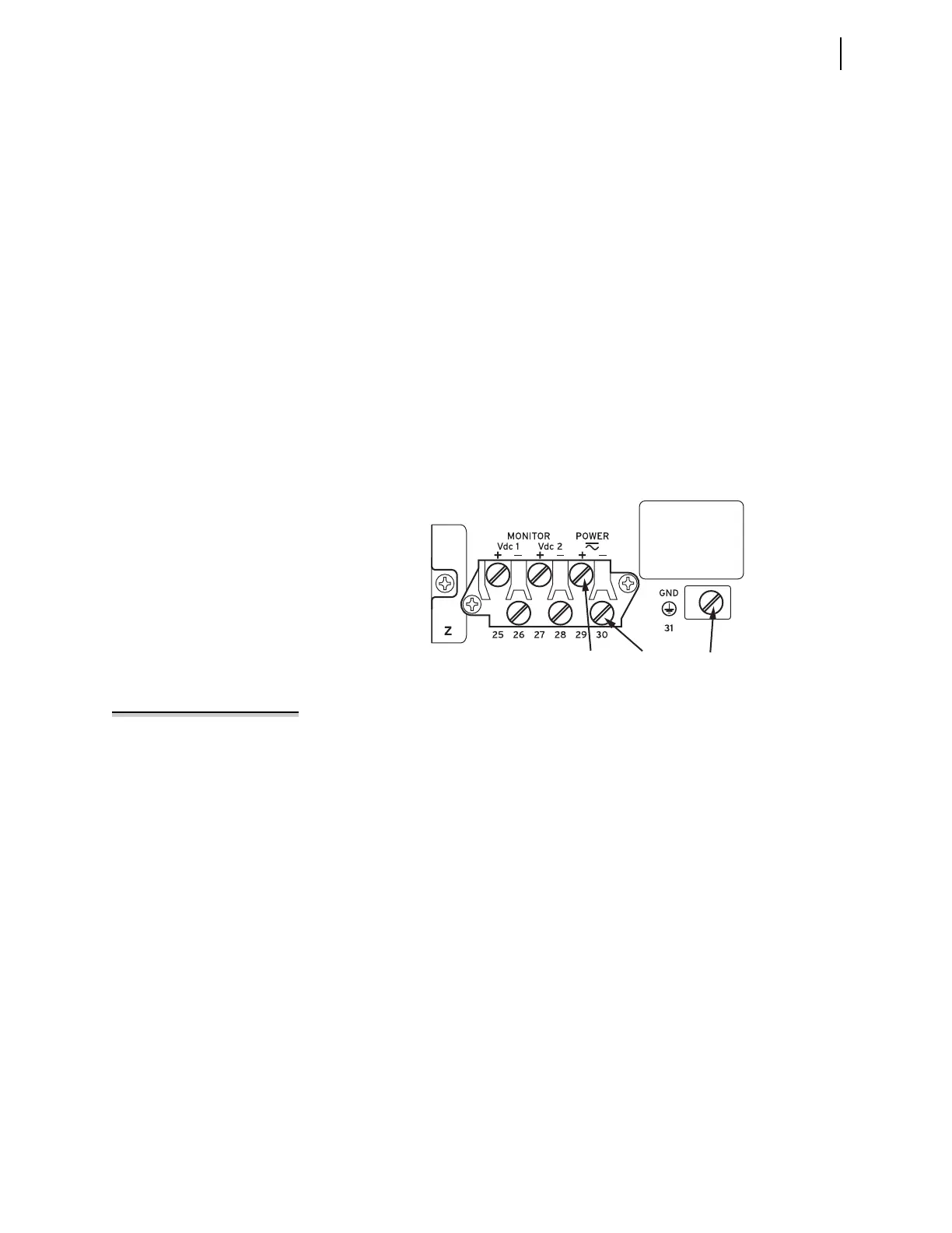
Connect the grounding terminal (#Z31) labeled GND on the rear panel to a rack
frame ground or main station ground for proper safety and performance.
This protective earthing terminal is in the lower right side of the relay panel (see
Figure 2.23 through Figure 2.32). The symbol that indicates the grounding termi-
nal is shown in Figure 2.33.
Use 2.5 mm
2
(14 AWG) or larger wire less than 2 m (6.6 feet) in length for this
connection. This terminal connects directly to the internal chassis ground of the
SEL-421.
Power Connections
The terminals labeled POWER on the rear panel (#Z29 and #Z30) must connect to a
power source that matches the power supply characteristics that your SEL-421
specifies on the rear-panel serial number label. (See Power Supply on page 1.14,
for complete power input specifications.) For the relay models that accept dc
input, the serial number label specifies dc with the symbol shown in Figure 2.33.
NOTE: The combined voltages
applied to the POWER and MONITOR
terminals must not exceed 600 V (rms
or dc).
The POWER terminals are isolated from chassis ground. Use 0.8 mm
2
(18 AWG)
or larger size wire to connect to the POWER terminals. Connection to external
power must comply with IEC 60947-1 and IEC 60947-3 and must be identified
as the disconnect device for the equipment.
Place an external disconnect device, switch/fuse combination, or circuit breaker
in the POWER leads for the SEL-421; this device must interrupt both the hot (H/+)
and neutral (N/–) power leads. The current rating for the power disconnect circuit
breaker or fuse must be 20 A maximum. Be sure to locate this device within 3.0
m (9.8 feet) of the relay.
Operational power is internally fused by power supply fuse F1. Table 2.11 lists
the SEL-421 power supply fuse requirements. Be sure to use fuses that comply
with IEC 127-2.
You can order the SEL-421 with one of three operational power input ranges
listed in Table 2.11. Each of the three supply voltage ranges represents a power
supply ordering option. As noted in Table 2.11, model numbers for the relay with
these power supplies begin 04214n (or 04215n), where n is 2, 4, or 6, to indicate
low, middle, and high voltage input power supplies, respectively. Note that each
power supply range covers two widely used nominal input voltages. The
SEL-421 power supply operates from 30 Hz to 120 Hz when ac power is used for
the POWER input.
Figure 2.36 Power Connection Area of the Rear Panel
Terminal Z29 Terminal Z30 Terminal Z31
Serial
Number
Label