5.158
SEL-421 Relay Instruction Manual Date Code 20171021
Protection Functions
Synchronism Check
Synchronism Check
NOTE: If the relay is using a remote
data acquisition system, such as TiDL,
the operating times will be delayed by
1.5 ms. Use caution when setting the
relay for synchronism check to
account for this added delay.
Synchronism-check elements prevent circuit breakers from closing if the corre-
sponding phases across the open circuit breaker are excessively out of phase. The
synchronism-check elements selectively close circuit breaker poles under the fol-
lowing criteria:
The systems on both sides of the open circuit breaker are in phase (within a
settable voltage angle difference), and one of the following is true:
➤ The voltages on both sides of the open circuit breaker are healthy
(within a settable voltage magnitude window).
➤ The difference between the voltages on both sides of the open circuit
breaker are less than a set limit.
➤ The voltages on both sides are healthy and the difference voltage is
less than a set limit.
You can use synchronism-check elements to program the relay to supervise cir-
cuit breaker closing; include the synchronism-check element outputs in the close
SEL
OGIC control equations. These element outputs are Relay Word bits
25W1BK1, 25A1BK1, 25W2BK1, 25A2BK1, 25W1BK2, 25A1BK2,
25W2BK2, and 25A2BK2 (see Synchronism-Check Logic Outputs on page 5.160
and Angle Checks and Synchronism-Check Element Outputs on page 5.168).
An example best demonstrates the synchronism-check capability in the relay.
This subsection presents a typical synchronism-check system.
Generalized System
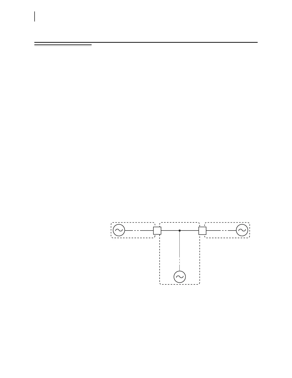
The generalized system single-line drawing in Figure 5.118 shows a partial cir-
cuit breaker-and-a-half or ring-bus substation arrangement. Presuming that both
Circuit Breakers BK1 and BK2 are open, the system is split into three sections:
Bus 1, Bus 2, and Line.
Paralleled and Asynchronous Systems
Figure 5.118 shows remote sources for each section. Often, a portion of the
power system is paralleled beyond the open Circuit Breakers BK1 and BK2; the
remote sources are really the same aggregate source. If the aggregate source is
much closer to one side of the open circuit breaker than the other, there is a
Figure 5.118 Partial Breaker-and-a-Half or Partial Ring-Bus Breaker
Arrangement