2.30
SEL-421 Relay Instruction Manual Date Code 20171021
Installation
Connection
Rear-Panel Symbols
There are important safety symbols on the rear of the SEL-421 (see Figure 2.33).
Observe proper safety precautions when you connect the relay at terminals
marked by these symbols. In particular, the danger symbol located on the rear
panel corresponds to the following: Contact with instrument terminals can cause
electrical shock that can result in injury or death. Be careful to limit access to
these terminals.
Screw-Terminal Connectors
Terminate connections to the SEL-421 screw-terminal connectors with ring-type
crimp lugs. Use a #8 ring lug with a maximum width of 9.1 mm (0.360 in.). The
screws in the rear-panel screw-terminal connectors are #8-32 binding head, slot-
ted, nickel-plated brass screws. Tightening torque for the terminal connector
screws is 1.0 Nm to 2.0 Nm (9 in-lb. to 18 in-lb.).
You can remove the screw-terminal connectors from the rear of the SEL-421 by
unscrewing the screws at each end of the connector block. Perform the following
steps to remove a screw-terminal connector:
Step 1. Remove the connector by pulling the connector block straight out.
Note that the receptacle on the relay circuit board is keyed; you can
insert each screw-terminal connector in only one location on the rear
panel.
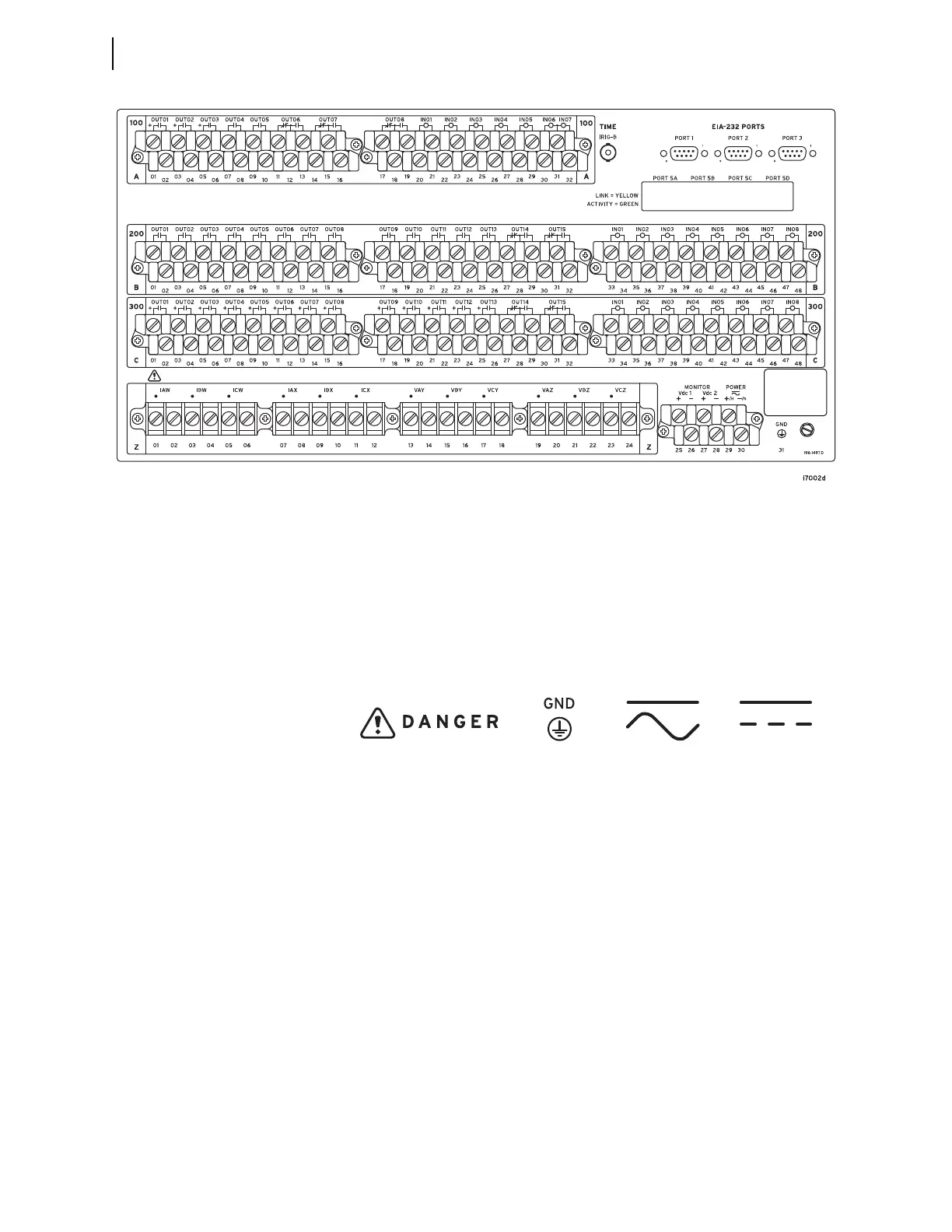
Figure 2.32 5U Rear Panel, Main Board, INT2 and INT7 I/O Interface Board
Figure 2.33 Rear-Panel Symbols
Danger (Caution,
risk of danger)
Symbol
Grounding
Terminal
Symbol
DC Input SymbolAC/DC Input Symbol