5.152
SEL-421 Relay Instruction Manual Date Code 20171021
Protection Functions
Circuit Breaker Failure Protection
Retrip Scheme Y2 Single Pole (Setting EBFL = Y2)
The logic shown in Figure 5.112 applies to three-pole breaker configurations.
Scheme Y2 is similar to Scheme 2, but the current check (50FA1) is now part of
the Retrip Time delay (RTPU1).
Circuit Breaker Failure Initiation Dropout and Seal-In
The SEL-421 circuit breaker failure protection features breaker failure initiation
extension and a breaker failure seal-in latch. The lower portion of Figure 5.114
shows the dropout and seal-in logic.
Dropout Delay
Set timer BFIDO1 (Breaker Failure Initiate Dropout Delay—BK1) to stretch a
short pulsed circuit breaker failure initiation. Use this feature for protecting dual
circuit breakers when separate 86 BF lockout relays have differing energizing
times.
Seal-In Delay
Set timer BFISP1 (Breaker Failure Initiate Seal-In Delay—BK1) to qualify
extended circuit breaker failure initiation latch seal-in. When you set BFISP1
longer than BFIDO1 and the circuit breaker failure initiate is greater than the dif-
ference of the two timers, the relay seals in the circuit breaker failure extended
initiation after the initiate signal deasserts until the BFIDO1 time expires and all
50Fn elements deassert.
No Current/Residual Current Circuit Breaker Failure Protection Logic
The SEL-421 has separate circuit breaker failure logic that operates on zero-
sequence current rather than phase current. Use this logic to detect a circuit
breaker failure and take appropriate action when a weak source drives the fault or
if the protected circuit breaker fails to trip during a high-resistance ground fault.
The residual current input to this logic is the 50R1 residual overcurrent element
(see Figure 5.113). Setting 50RP1 (Residual Current Pickup—BK1) is the pickup
threshold setting for the 50R1 element.
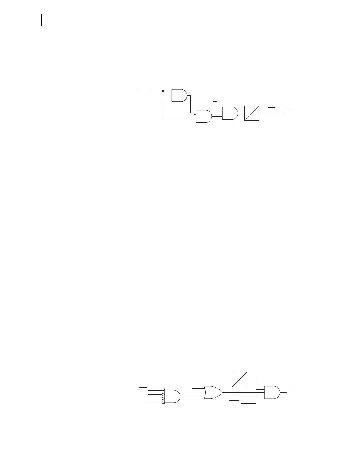
Figure 5.112 Scheme Y2 Current-Supervised Single-Pole Retrip Logic
BFIA1
BFIB1
BFIC1
RTA1
RTSA1
Relay
Word
Bit
Relay
Word
Bits
SEL
OGIC
Settings
RTPU1
0
2 of 3
50FA1
Figure 5.113 No Current/Residual Current Circuit Breaker Failure Protection
Logic Diagram
50R1
B1OPHA
B1OPHB
B1OPHC
BFI3P1
BFIN1
ENCBF1 := Y
NBF1
Relay
Word
Bits
Relay
Word
Bit
SELOGIC
Settings
Setting
NPU1
0