2.45
Date Code 20171021 Instruction Manual SEL-421 Relay
Installation
Connection
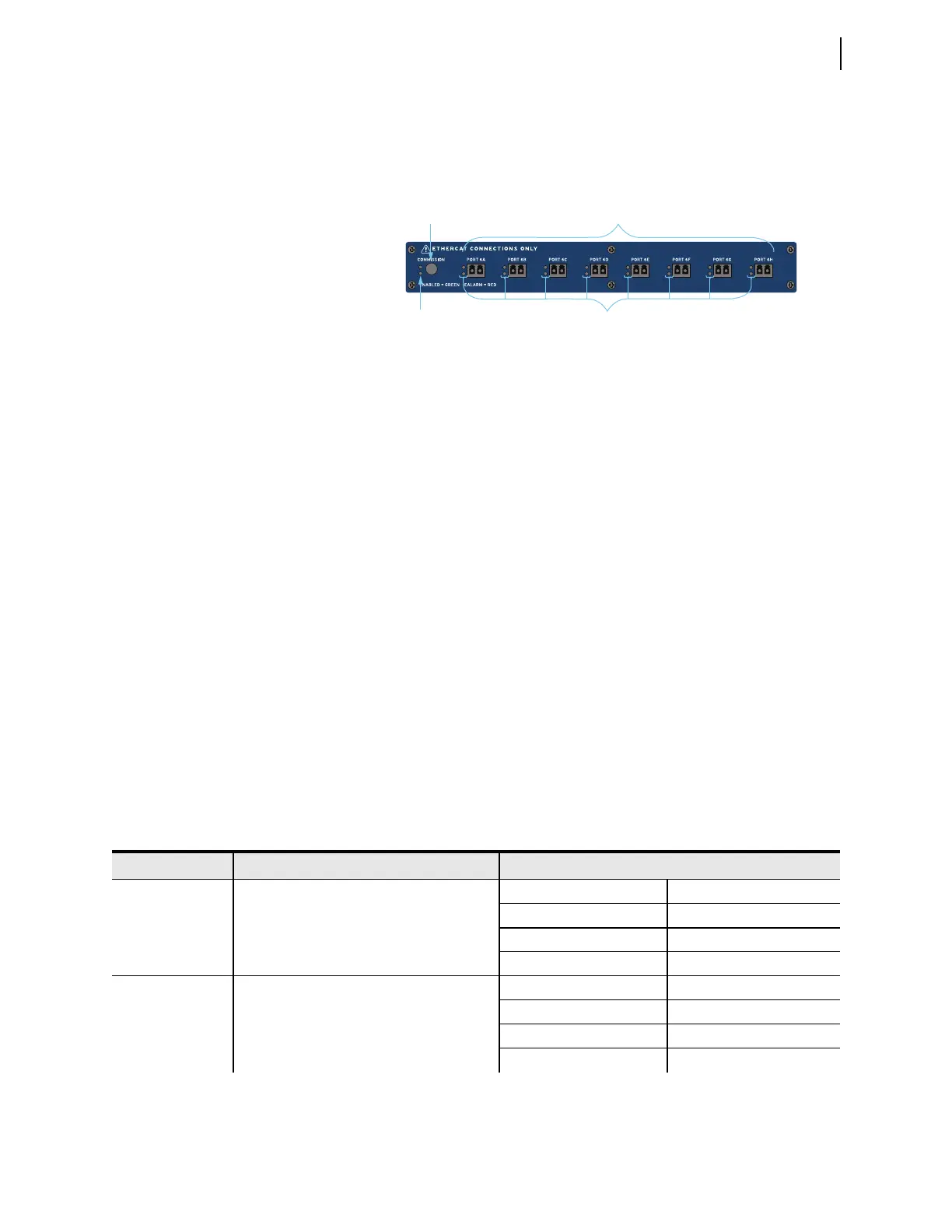
The SEL-421 has a new interface on its back panel that replaces the original CT
and PT input connections. These standard inputs are replaced with a remote mod-
ule interface that supports eight fiber ports, labeled PORT 6A–PORT 6H (see
Figure 2.46).
Once all the remote Axion nodes are connected to the relay, press the COMMISSION
pushbutton on the Remote Module Interface. This process verifies that the con-
nected ports and Axion nodes are installed according to one of the supported
topologies. Once the process is complete, the topology is stored in memory. At
each additional startup of the relay, the firmware validates that the connected
modules match those of the stored configuration. It recognizes whether any of the
CT/PT modules within the node have changed. If the topology needs to be
changed (e.g., modules are added or replaced), the system will need to be recom-
missioned by pressing the COMMISSION pushbutton.
When the commissioning and validation of the topology is complete, the voltages
and currents map according to the topology assignments (see Topologies on
page 2.42). Secondary injection testing takes place at each Axion node. Test
sources must inject voltages and currents to the Axion node to verify correct
installation and mapping. Monitoring of the voltages and currents remains in the
control house with the relay.
LED Status
As shown in Figure 2.46, the TiDL relay provides LED status indication about
the network and configuration. Once the system is connected, and the COMMISSION
pushbutton is pressed, the LEDs will provide the status of the commissioning
process. Table 2.12 shows the status of the rear-panel LEDs for each commis-
sioning state.
Figure 2.46 Remote Module Interface
Commissioning
Button
Commission LED
for Network Status
Eight Fiber-Optic 100 Mbps
EtherCAT Ports
LEDs for Remote
Node Status
Table 2.12 TiDL LED Status (Sheet 1 of 2)
State Description LED Status
Initial State Determining if topology exists Green COMMISSION LED OFF
Red COMMISSION LED ON
Green LED: PORT 6A–PORT 6H OFF
Red LED: PORT 6A–PORT 6H ON
Verify Topology Determining if topology is supported Green COMMISSION LED Blinking
Red COMMISSION LED ON
Green LED: PORT 6A–PORT 6H Blinking
Red LED: PORT 6A–PORT 6H ON