2.46
SEL-421 Relay Instruction Manual Date Code 20171021
Installation
Connection
IRIG-B Input Connections
The SEL-421 accepts a demodulated IRIG-B signal through two types of rear-
panel connectors. These IRIG-B inputs are the BNC connector labeled IRIG-B and
Pin 4 (+) and Pin 6 (–) of the DB-9 rear-panel serial port labeled PORT 1. When you
use the PORT 1 input, ensure that you connect Pins 4 and 6 with the proper polarity.
See Communications Ports Connections on page 2.47 for other DB-9 connector
pinouts and additional details.
These inputs accept the dc shift time code generator output (demodulated)
IRIG-B signal with positive edge on the time mark. For more information on
IRIG-B and the SEL-421, see IRIG-B Inputs on page 2.12.
The PORT 1 IRIG-B input connects to a 2.5 k grounded resistor and goes
through a single logic signal buffer. The PORT 1 IRIG-B is equipped with robust
ESD and overvoltage protection but is not optically isolated. When you are using
the PORT 1 input, ensure that you connect Pin 4 (+) and Pin 6 (–) with the proper
polarity.
The IRIG network should be properly terminated with an external termination
resistor (SEL 240-1802, BNC Tee, and SEL 240-1800, BNC terminator, 50 ohm)
placed on the unit that is farthest from the source. This termination provides
impedance matching of the cable for the best possible signal-to-noise ratio.
Where distance between the SEL-421 and the IRIG-B sending device exceeds the
cable length recommended for conventional EIA-232 metallic conductor cables,
you can use transceivers to provide isolation and to establish communication to
remote locations.
Conventional fiber-optic and telephone modems do not support IRIG-B signal
transmission. The SEL-2810 Fiber-Optic Transceiver/Modem includes a channel
for the IRIG-B time code. These transceivers enable you to synchronize time pre-
cisely from IRIG-B time code generators (such as the SEL-2032 Communica-
tions Processor) over a fiber-optic communications link.
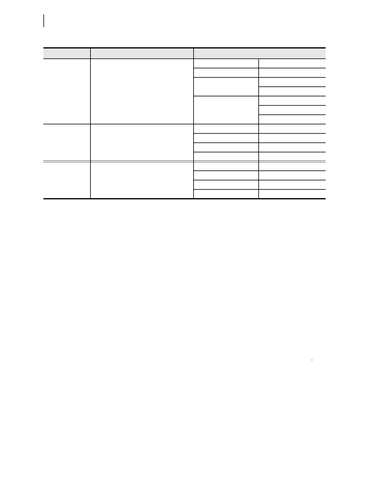
Topology Mismatch Connection does not match supported topology Green COMMISSION LED Blinking
Red COMMISSION LED ON
Green LED: PORT 6A–PORT 6H OFF—mismatched/unused
ON—matched
Red LED: PORT 6A–PORT 6H Blinking—mismatched
ON—matched
OFF—ports unused
Topology Matched Connection matches topology Green COMMISSION LED ON
Red COMMISSION LED OFF
Green LED: PORT 6A–PORT 6H ON
Red LED: PORT 6A–PORT 6H OFF
N/A A commissioned port experiences an error Green COMMISSION LED ON
Red COMMISSION LED OFF
Green LED: PORT 6A–PORT 6H ON
Red LED: PORT 6A–PORT 6H Blinking—failed port
Table 2.12 TiDL LED Status (Sheet 2 of 2)
State Description LED Status