5.33
Date Code 20171021 Instruction Manual SEL-421 Relay
Protection Functions
Fault Type Identification Selection Logic
Fault Type Identification Selection Logic
The fault type identification selection (FIDS) logic is enabled by the Group Set-
ting EFID. This logic identifies the faulted phase(s) for all faults involving
ground by comparing the angle between I
0
and I
2
.
For cases where only zero-sequence current flows through the relay terminal
(that is, no negative-sequence current and no positive-sequence current), the
(FIDS) logic uses single-phase undervoltage elements for faulted phase selection.
The FIDS logic is not active during a single pole-open (SPO) condition (i.e.,
when SPO equals logical 1).
Setting EFID should be set equal to N only when the relay is applied in high-
resistance grounded transmission systems. These systems can challenge the oper-
ation of the FIDS logic for phase-to-phase-to-ground faults. Setting EFID equal
to N disables the FIDS logic, thereby removing FIDS supervision of phase-
distance elements.
For all other applications, EFID must be set equal to Y to ensure proper operation
of the phase and ground-distance elements.
Ground Directional Element
The SEL-421 offers a choice of three independent directional elements to super-
vise the ground-distance elements and directional residual ground overcurrent
elements (67Gn, where n equals 1 through 4) during ground faults. You can also
use the ground directional element for torque control. Internal logic selects the
best choice automatically. Table 5.31 lists the directional elements the relay uses
to provide ground directional decisions.
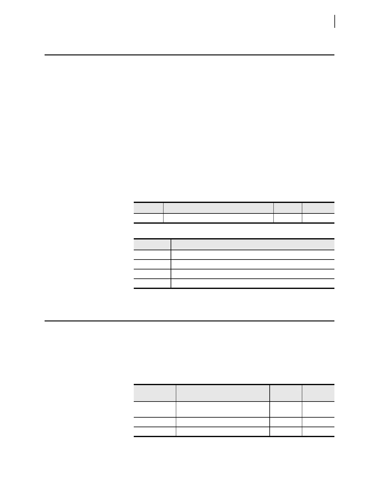
Table 5.29 Fault Type Identification Logic Settings
Setting Prompt Range Default
EFID Enable fault identification logic Y, N Y
Ta b l e 5 . 3 0 FID S Re l a y Word Bi t s
Name Description
FIDEN FIDS logic enabled
FSA A-Phase-to-ground fault or B-Phase to C-Phase-to-ground fault selected
FSB B-Phase-to-ground fault or C-Phase to A-Phase-to-ground fault selected
FSC C-Phase-to-ground fault or A-Phase to B-Phase-to-ground fault selected
Table 5.31 Directional Elements Supervising Ground Elements
Directional
Elements
Description
Forwa rd
Output
Reverse
Output
32QG Negative-sequence voltage polarized for
ground faults
F32QG R32QG
32V Zero-sequence voltage polarized F32V R32V
32I Zero-sequence current polarized F32I R32I