5.160
SEL-421 Relay Instruction Manual Date Code 20171021
Protection Functions
Synchronism Check
Setting E25BK
n
:= Y2
If E25BKn is set to Y2, where n = 1 or 2, the synchronizing logic verifies that
both the reference and synchronizing voltages are healthy and that the difference
between them is less than the 25VDIF setting before enabling the synchronism-
check logic. It combines the logic that is used when E25BKn is set to Y or Y1.
Synchronism-Check Settings Example
This example uses a two-circuit breaker arrangement (see Figure 5.119). Set the
synchronism-check enable settings:
E25BK1 := Y. Synchronism Check for Circuit Breaker BK1 (Y, N, Y1, Y2)
E25BK2 := Y. Synchronism Check for Circuit Breaker BK2 (Y, N, Y1, Y2)
NOTE: If Global setting NUMBK = 1,
the synchronism-check logic is not
executed for Breaker 2.
If you are using the relay on a single circuit breaker, enable synchronism check
for only one circuit breaker (E25BK1 := Y and E25BK2 := N).
Figure 5.120 shows the correspondence between the synchronism-check settings
and the two-circuit breaker application example. All of these settings are listed in
Section 10: Settings. The following subsections explain these settings and include
an explanation of Alternative Synchronism-Check Voltage Source 2 settings (see
Figure 5.131).
Synchronism-Check Logic Outputs
Figure 5.121 shows the correspondence between synchronism-check logic out-
puts (Relay Word bits) and the two-circuit breaker arrangement. These Relay
Word bits assert to logical 1 (e.g., 59VP equals logical 1) if true and deassert to
logical 0 (e.g., 59VS1 equals logical 0) if false. Table 5.81 lists these Relay Word
bits.
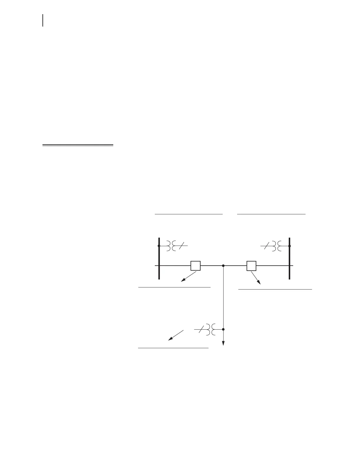
Figure 5.120 Synchronism-Check Settings
Bus 2
Bus 1
Line
BK2
BK1
Synchronism-Check Voltage Source 1
SYNCS1 — designate voltage input
KS1M — adjust magnitude to reference
KS1A — adjust angle to reference
Synchronism-Check Voltage Reference
SYNCP — designate voltage input
25VL — voltage window/low threshold
25VH — voltage window/high threshold
Synchronism-Check Across Breaker BK2
25SFBK2 — max. slip frequency
ANG1BK2 — max. angle difference 1
ANG2BK2 — max. angle difference 2
TCLSBK2 — breaker close time
BSYNBK2 — block synch check (SEL
OGIC)
Synchronism-Check Across Breaker BK1
25SFBK1 — max. slip frequency
ANG1BK1 — max. angle difference 1
ANG2BK1 — max. angle difference 2
TCLSBK1 — breaker close time
BSYNBK1 — block synch check (SEL
OGIC)
Synchronism-Check Voltage Source 2
SYNCS2 — designate voltage input
KS2M — adjust magnitude to reference
KS2A — adjust angle to reference
1
3
1
. . .
. . .
. . .