6.90
SEL-421 Relay Instruction Manual Date Code 20171021
Protection Applications Examples
EHV Parallel 230 kV Underground Cables Example
Current and Voltage Source Selection
The voltage and current source selection is for one circuit breaker. The relay
derives the line current source from current input IW when you set ESS to N.
ESS := N. Current and Voltage Source Selection (Y, N, 1, 2, 3, 4)
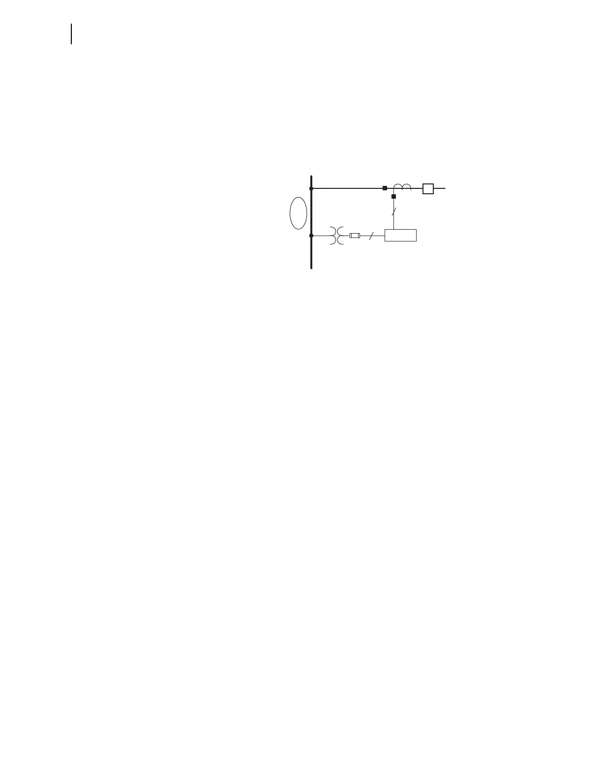
Figure 6.20 illustrates the current and voltage sources for this particular applica-
tion. The relay uses potential input VY and current input IW for line relaying.
Breaker Monitor
Circuit Breaker Configuration
Set the Circuit Breaker BK1 type for a three-pole trip circuit breaker.
BK1TYP := 3. Breaker 1 Trip Type (Single-Pole = 1, Three-Pole = 3)
Circuit Breaker 1 Inputs
The SEL-421 uses a normally open auxiliary contact (52A) from the circuit
breaker to determine whether the circuit breaker is open or closed.
52AA1 := IN101. N/O Contact Input—BK1 (SELOGIC Equation)
Group Settings
Line Configuration
The SEL-421 has four transformer turns ratio settings that convert the secondary
potentials and current s the relay measures to the corresponding primary values.
These settings are the potential transformer and current transformer ratios (PTRY,
PTRZ, CTRW, and CTRX). Use the VY potential input for line relaying; these
come from the bus potentials (see Figure 6.20). Use the IW current input for line
current. Relay setting VNOMY is the nominal secondary line-to-line voltage of
the potential transformers.
PTRY := 2000. Potential Transformer Ratio—Input Y (1–10000)
VNOMY := 115. PT Nominal Voltage (L–L)—Input Y (60–300 V secondary)
CTRW := 200. Current Transformer Ratio—Input W (1–50000)
Figure 6.20 Circuit Breaker Arrangement at Station S, Cable 1
SEL-421
3
3
(Bus Potential)
230 kV
VY
IW
BK1