2.10
SEL-421 Relay Instruction Manual Date Code 20171021
Installation
Shared Configuration Attributes
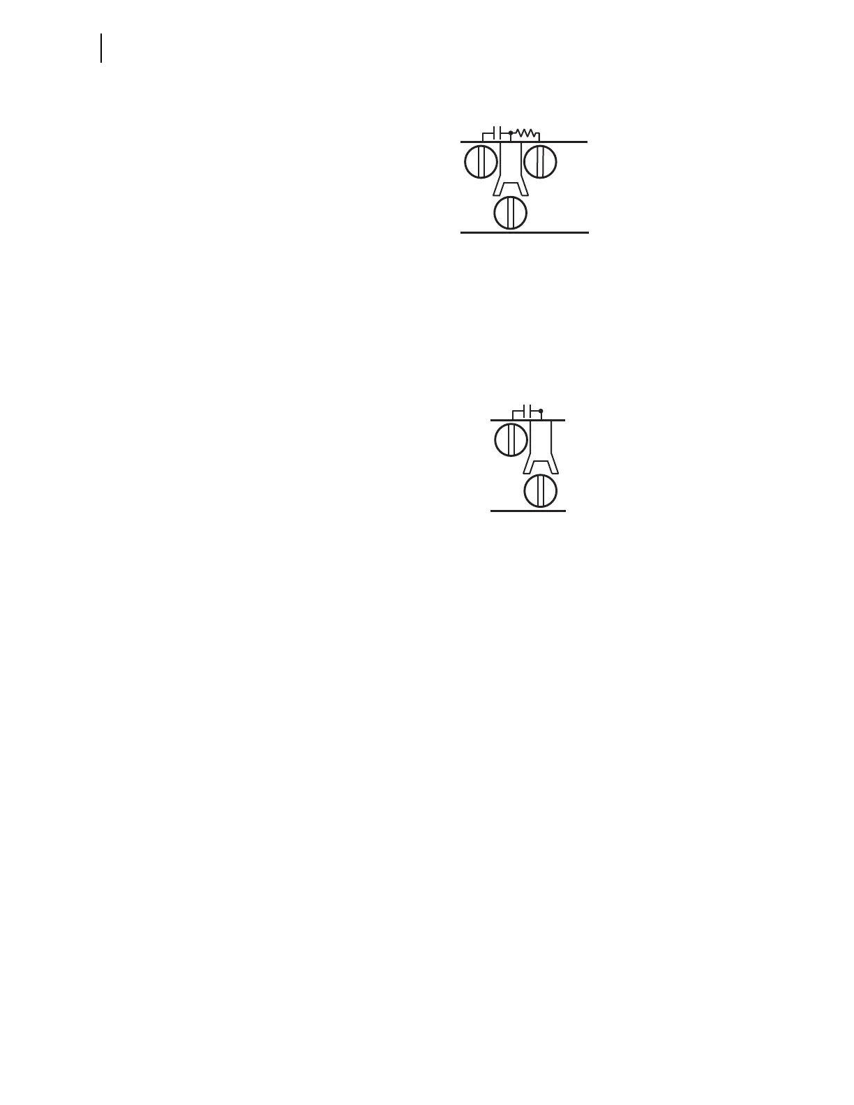
Figure 2.7 shows a representative connection for a Form A high-speed, high-cur-
rent interrupting control output on the INT4 I/O interface terminals. The HS
marks are included to indicate that this is a high-speed control output.
The INT5 (INT8) high-speed, high-current interrupting control output uses three
terminal positions, while the INT4 high-speed, high-current interrupting uses
two. The third terminal of each INT5 (INT8) high-speed, high-current interrupt-
ing control output is connected to precharge resistors that can be used to mitigate
transient inrush current conditions, as explained below. A similar technique can
be used with INT4 board high-speed, high-current interrupting control outputs
using external resistors.
Short transient inrush current can flow at the closing of an external switch in
series with open high-speed, high-current interrupting contacts. This transient
will not energize the circuits in typical relay-coil control applications (trip coils
and close coils), and standard auxiliary relays will not pick up. However, an
extremely sensitive digital input or light-duty, high-speed auxiliary relay can pick
up for this condition. This false pickup transient occurs when the capacitance of
the high-speed, high-current interrupting output circuitry charges (creating a
momentary short circuit that a fast, sensitive device sees as a contact closure). A
third terminal (03 in Figure 2.8) provides an internal path for precharging the
high-speed, high-current interrupting output circuit capacitance when the circuit
is open.
Figure 2.6 High-Speed, High-Current Interrupting Control Output Connection,
INT5 (INT8)
Figure 2.7 High-Speed, High-Current Interrupting Control Output Connection,
INT4