6.19
Date Code 20171021 Instruction Manual SEL-421 Relay
Protection Applications Examples
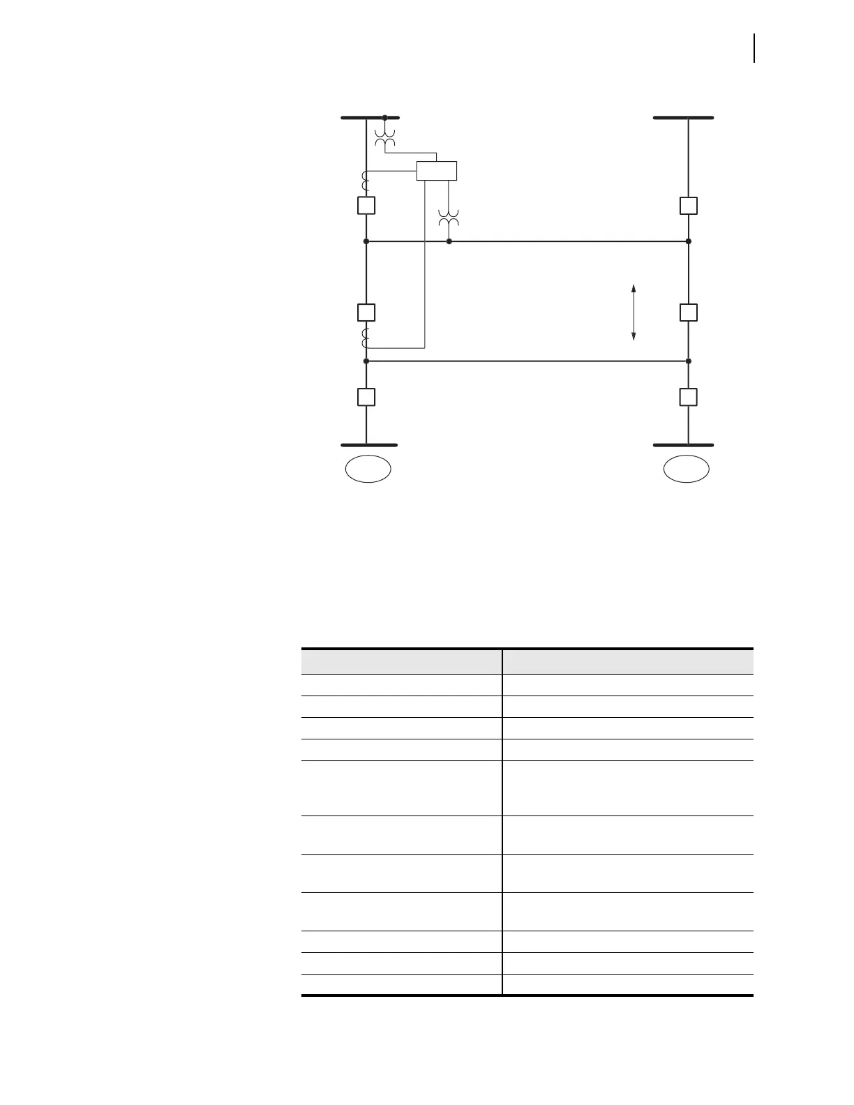
500 kV Parallel Transmission Lines With Mutual Coupling Example
Power System Data
Table 6.7 lists the power system data for this application example. Substitute the
values and parameters that correspond to your system when you set the relay
using this example as a guide.
Figure 6.3 500 kV Parallel Overhead Transmission Lines
L
L
1
Z0
S
Moscow
R
Pullman
Lin
Lin
B
B
EL-42
k
k
Table 6.7 System Data—500 kV Parallel Overhead Transmission Lines
Parameter Value
Nominal system line-to-line voltage 500 kV
Nominal relay current 5 A secondary
Nominal frequency 60 Hz
Line length 75 miles
Line impedances:
Z
1L1
= Z
1L2
Z
0L1
=Z
0L2
44.78 87.6° primary
162.9 82.1° primary
Zero-sequence mutual coupling:
Z
0M
88.35 76.6° primary
Source S impedances:
Z
1S
= Z
0S
50 88° primary
Source R impedances:
Z
1R
= Z
0R
20 88° primary
PTR (Potential transformer ratio) 500 kV:111.11 V = 4500
CTR (Current transformer ratio) 2000:5 = 400
Phase rotation ABC