8.13
Date Code 20171021 Instruction Manual SEL-421 Relay
Settings
Group Settings
Recloser and Manual Closing Table 8.74
Single-Pole Reclose Settings Table 8.75
Three-Pole Reclose Settings Table 8.76
Voltage Elements Table 8.77
Demand Metering Table 8.78
M
IRRORED BITS Communications Settings Table 8.79
Trip Logic Table 8.80
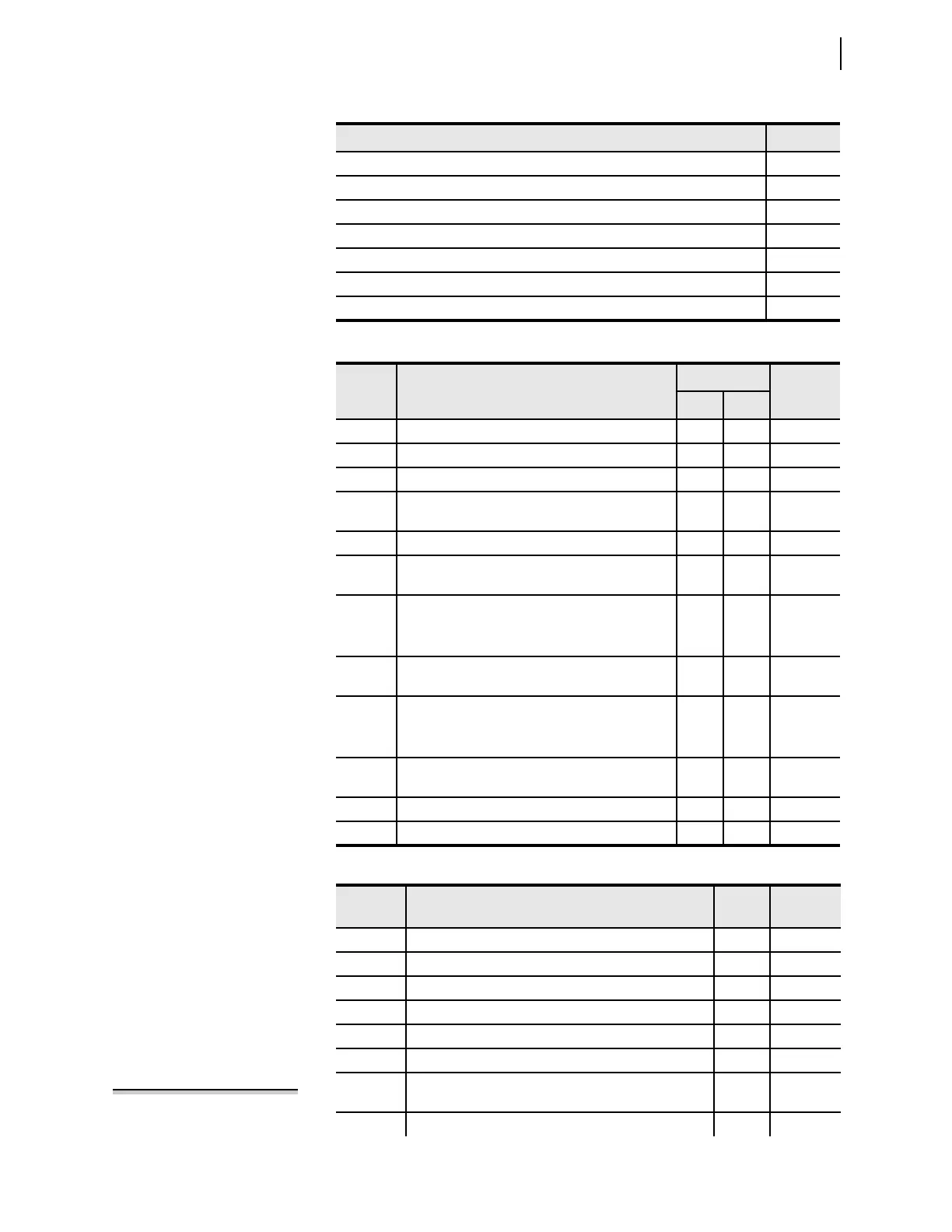
Table 8.35 Line Configuration
Setting Prompt
Default Value
Increment
5 A 1 A
CTRW Current Transformer Ratio—Input W (1–50000) 200 200 1
CTRX Current Transformer Ratio—Input X (1–50000) 200 200 1
PTRY Potential Transformer Ratio—Input Y (1–10000) 2000 2000.0 0.1
VNOMY PT Nominal Voltage (L-L)—Input Y
(60–300 V secondary)
115 115 1
PTRZ Potential Transformer Ratio—Input Z (1–10000) 2000 2000.0 0.1
VNOMZ PT Nominal Voltage (L-L)—Input Z
(60–300 V secondary)
115 115 1
Z1MAG Positive-Sequence Line Impedance Magnitude
(0.05–255 W secondary) 5 A
(0.25–1275 W secondary) 1 A
7.80 39.00 0.01
Z1ANG Positive-Sequence Line Impedance Angle
(5.00–90 degrees)
84.00 84.00 0.01
Z0MAG Zero-Sequence Line Impedance Magnitude
(0.05–255 W secondary) 5 A
(0.25–1275 W secondary) 1 A
24.80 124.00 0.01
Z0ANG Zero-Sequence Line Impedance Angle
(5.00–90 degrees)
81.50 81.50 0.01
EFLOC Fault Location (Y, N) Y Y
LL Line Length (0.10–999) 100.00 100.00 0.01
Table 8.36 Relay Configuration (Sheet 1 of 2)
Setting Prompt
Default
Value
Increment
EMBA Channel A MIRRORED BITS Enable (Y, N) N
EMBB Channel B M
IRRORED BITS Enable (Y, N) N
E21MP Mho Phase Distance Zones (N, 1–5) 3
E21XP Quadrilateral Phase Distance Zones (N, 1–5) 3
E21MG Mho Ground Distance Zones (N, 1–5) 3
E21XG Quadrilateral Ground Distance Zones (N, 1–5) N
ECVT Capacitive Voltage Transformer Transient Detection
(Y, N)
N
ESERCMP Series-Compensated Line Logic (Y, N) N
Table 8.34 Group Settings Categories (Sheet 2 of 2)
Settings Reference
NOTE: The SEL-421-4 does not
provide series-compensated line
protection logic. This setting is
unavailable in the SEL-421-4.