6.28
SEL-421 Relay Instruction Manual Date Code 20171021
Protection Applications Examples
500 kV Parallel Transmission Lines With Mutual Coupling Example
Zone 1 Reactance
Zone 1 quadrilateral ground-distance reactance reach must meet the same
requirement as that for Zone 1 mho phase-distance protection; the reach setting
should be no greater than 80 percent of the line.
XG1 = 0.8 • Z
1L1
= 3.18
XG1 := 3.18. Zone 1 Reactance (OFF, 0.05–64 secondary)
Zone 1 Resistance
Find RG1 (Zone1 resistance) from the per-unit reach m of the Zone 1 reactance.
Use Equation 6.9, which is Equation 3 in Appendix A—Quadrilateral Reactive
Reach Versus Resistive Reach Setting Guideline from the paper Digital Commu-
nications for Power System Protection: Security, Availability, and Speed. You can
find a copy of this paper on the SEL website at selinc.com.
Equation 6.9
XG1 is set at 80 percent of the transmission line (i.e., m = 0.8 per-unit); the posi-
tive-sequence reactance of the overhead transmission line X
1L1
is 3.977 sec-
ondary (from the rectangular form of Z
1L1
in Table 6 .8 ).
Equation 6.10
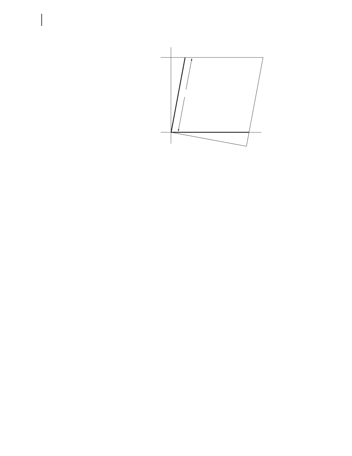
Figure 6.5 Quadrilateral Ground-Distance Element Reactive Reach Setting
where:
m = per-unit reach of XG1
R = RG1, the Zone 1 resistance
X
1L1
= positive-sequence transmission line reactance
m1
R
X
1L1
• 20
------------------------–=
Z
1L1
3.98 87.6=
R
1L1
jX
1L1
+=
0.167 j3.977+=