2.11
Date Code 20171021 Instruction Manual SEL-421 Relay
Installation
Shared Configuration Attributes
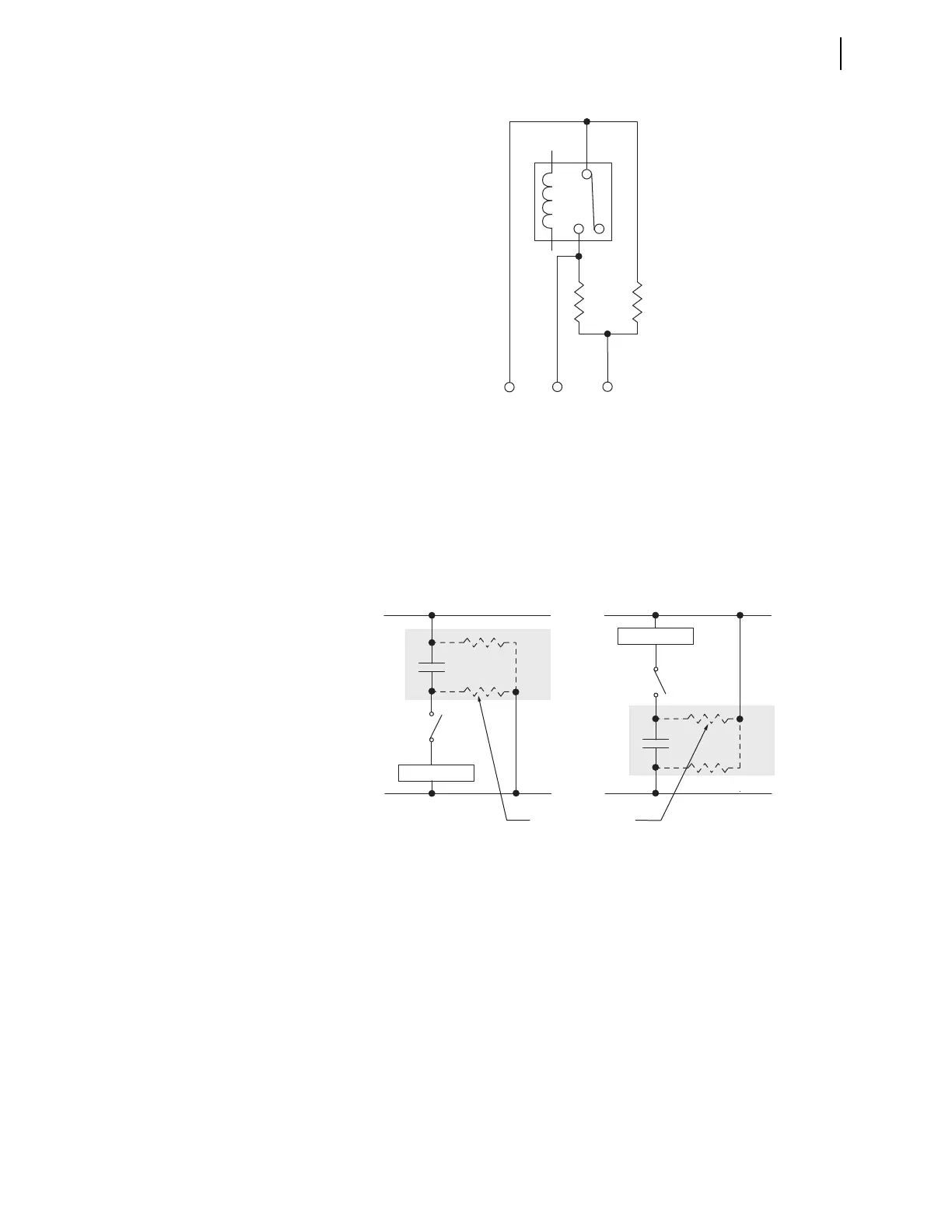
Figure 2.9 shows some possible connections for this third terminal that will elim-
inate the false pick-up transients when closing an external switch. In general, you
must connect the third terminal to the dc rail (positive or negative) that is on the
same side as the open external switch condition. If an open switch exists on either
side of the output contact, then you can accommodate only one condition because
two open switches (one on each side of the contact) defeat the precharge circuit.
For wiring convenience, on the INT5 (INT8) I/O interface board, the precharge
resistors shown in Figure 2.8 are built-in to the I/O board, and connected to a
third terminal. On the INT4 I/O interface board, there are no built-in precharge
resistors, and each high-speed, high-current interrupting control output has only
two terminal connections.
Main Board I/O
The SEL-421 base model is a 3U chassis with I/O interface on the main board
(the top board). See Figure 2.2 and Figure 2.3 for representative rear-panel views
of the 3U chassis rear panel.
Figure 2.8 High-Speed, High-Current Interrupting Control Output Typical
Te r m i n a l s , I N T 5 ( I N T 8)
Figure 2.9 Precharging Internal Capacitance of High-Speed, High-Current
Interrupting Output Contacts, INT5 (INT8)
Load
Load
(+)
(+)
(–) (—)
Precharge circuit
path internal to high-speed
high-current interrupting
control output
01
02
02
01
03
03