5.21
Date Code 20171021 Instruction Manual SEL-421 Relay
Protection Functions
Time-Error Calculation
81D
n
P (Level
n
Pickup)
Set the value at which you want the frequency element for each of six levels to
assert. For a value of 81DnP less than the nominal system frequency NFREQ (50
or 60 Hz), the element operates as an underfrequency element. For a value greater
than NFREQ, the element operates as an overfrequency element. Note that n can
be one of six levels, 1–6.
81D
n
D (Level
n
Time Delay)
Select a time in seconds that you want frequency elements to wait before
asserting.
Time-Error Calculation
Description and Settings
The time-error calculation function in the SEL-421 measures the amount of time
that an ac clock running from the same line frequency measured by the relay
would differ from a reference clock. The relay integrates the difference between
the measured power system frequency and the nominal frequency (Global setting
NFREQ) to create a time-error analog quantity, TE.
NOTE: The LOADTE SELOGIC
equation is processed once per cycle.
A momentary assertion must be
conditioned to be at least one cycle in
duration. A rising edge operator
(R_TRIG) should not be used in the
LOADTE setting.
A correction feature allows the present time-error estimate (TE) to be discarded,
and a new value (TECORR) loaded when SEL
OGIC control equation LOADTE
asserts. For example, if the TECORR value is set to zero, and then LOADTE is
momentarily asserted, the TE analog quantity will be set to 0.000 seconds.
The TECORR analog quantity can be pre-loaded by the TEC command (see
TEC on page 14.54 in the SEL-400 Series Relays Instruction Manual), or via
DNP3, object 40, 41 index 01 (see Table 16.8 on page 16.12 in the SEL-400
Series Relays Instruction Manual). In either case, Relay Word bit PLDTE asserts
for approximately 1.5 cycles to indicate that the preload was successful.
A separate SEL
OGIC control equation, STALLTE, when asserted, causes time-
error calculation to be suspended.
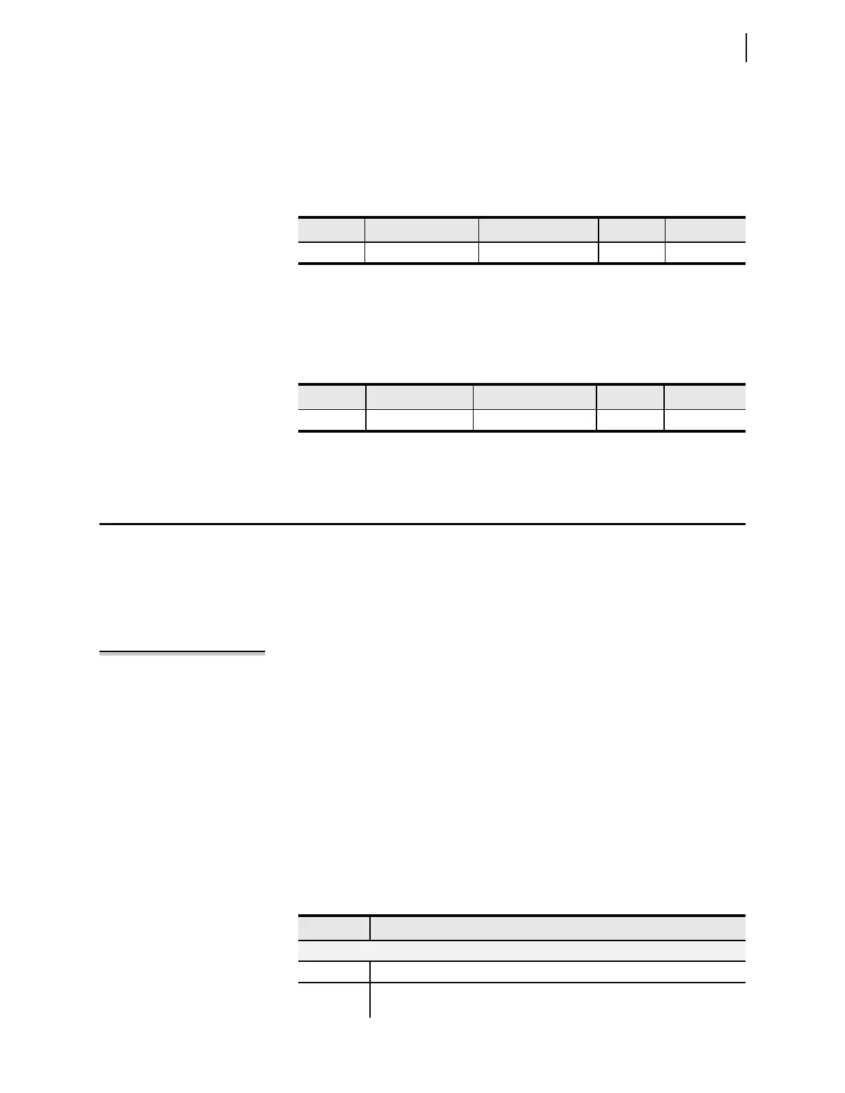
Table 5.18 lists the inputs and outputs of the time-error function.
Setting Prompt Range Default Category
81DnP
a
a
n
= 1–6.
Level n Pickup 40.01–69.99 Hz 61.00 Group
Setting Prompt Range Default Category
81DnD
a
a
n
= 1–6.
Level n Delay 0.04–400.00 sec 2 Group
Table 5.18 Time-Error Calculation Inputs and Outputs (Sheet 1 of 2)
INPUTS Description
Analog Quantities
FREQ Measured system frequency (see Tabl e 5 .16).
TECORR Time-error correction factor. This value can be preloaded via the TEC com-
mand, or DNP3.