1.8
SEL-421 Relay Instruction Manual Date Code 20171021
Introduction and Specifications
Applications
Applications
Use the SEL-421 in a variety of transmission line protection applications. For
information on connecting the relay, see Section 2: Installation. See Section 6:
Protection Applications Examples for a description of various protection applica-
tions using the SEL-421.
The figures in this subsection illustrate common relay application configurations.
Figure 1.2, Figure 1.3, Figure 1.4, Figure 1.5, Figure 1.6, and Figure 1.7 demon-
strate relay versatility with Global setting ESS (Current and Voltage Source
Selection). These figures show the power and simplicity of the four prepro-
grammed ESS options. For more information on setting ESS, see Current and
Voltage Source Selection on page 5.2.
The SEL-421 has two sets of three-phase analog current inputs, IW and IX, and
two sets of three-phase analog voltage inputs, VY and VZ. The drawings that fol-
low use a two-letter acronym to represent all three phases of a relay analog input.
For example, IW represents IAW, IBW, and ICW for A-, B-, and C-Phase current
inputs on terminal W, respectively. The drawings list a separate phase designator
if you need only one or two phases of the analog input set (VAZ for the A-Phase
voltage of the VZ input set, for example).
The SEL-421 supports remote data acquisition through use of the SEL-2240
Axion. The SEL Axion provides remote analog and digital data over an
IEC 61158 EtherCAT TiDL network. This technology provides low and deter-
ministic latency over a point-to-point architecture. The SEL-421 can receive as
many as eight fiber-optic links from as many as eight Axion remote data acquisi-
tion nodes. See Section 2: Installation for more details about TiDL applications.
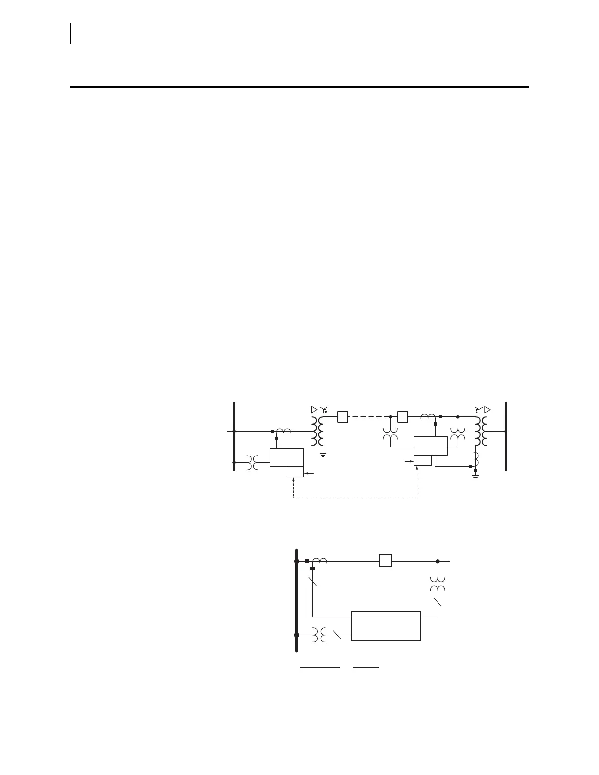
Figure 1.2 Protecting a Line Segment With MIRRORED BITS Communications on a
Fiber Channel
Figure 1.3 Single Circuit Breaker Configuration (ESS := 1)
SEL-421
Relay
CB
TX/RX
SEL-421
Relay
TX/RX
M
IRRORED
B
ITS
Communications
SEL-28XX
SEL-28XX
BUS 1
BUS 2
CB
SEL-421 Relay
BUS
CB1
3
3
IW
VAZ
VY
1
Analog Input
IW
VY
VAZ
Function
CB1 protection, line protection
Line protection
Synchronism check