2.15
Date Code 20171021 Instruction Manual SEL-421 Relay
Installation
Jumpers
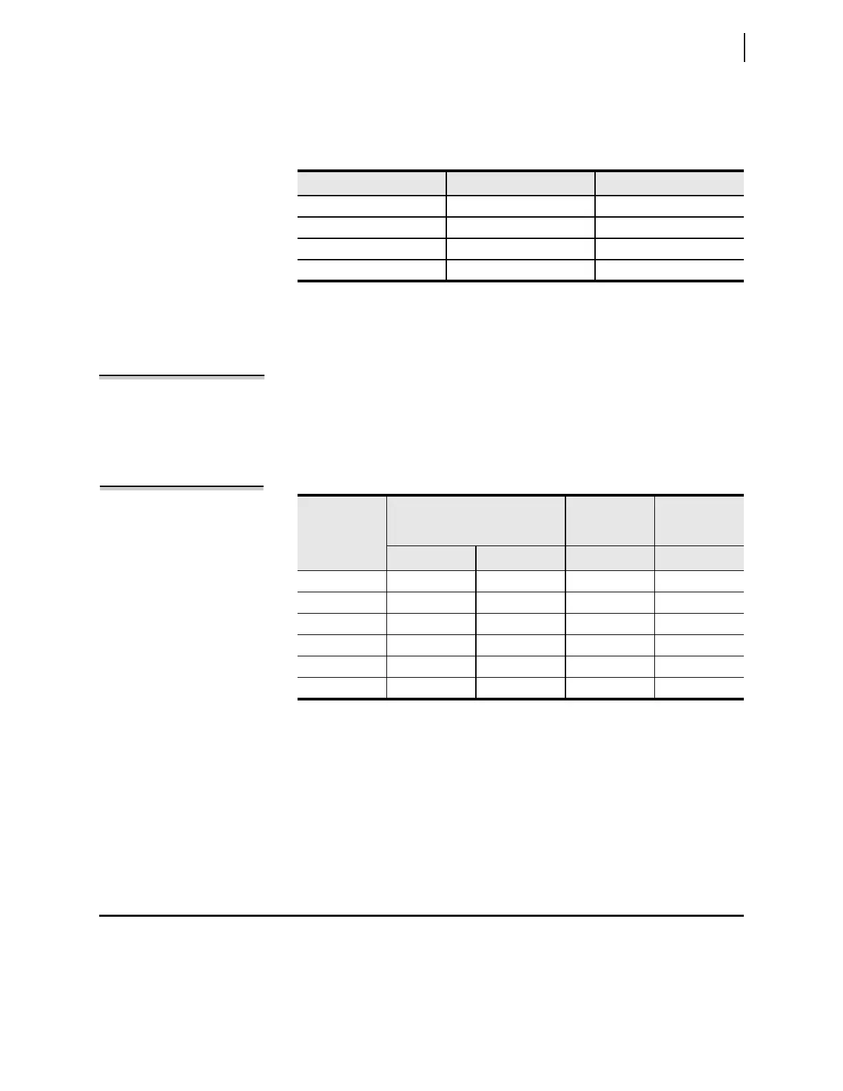
Table 2.3 is a comparison of the I/O board input capacities; the table also shows
the I/O inputs on the main board. See Control Inputs on page 1.15 for complete
control input specifications.
I/O Interface Board Outputs
NOTE: Form A control outputs
cannot be jumpered to Form B.
The I/O interface boards vary by the type and amount of output capabilities.
Table 2.4 lists the outputs of the additional I/O interface boards; the table also
shows the I/O outputs on the main board. Information about the standard and
hybrid (high-current interrupting) control outputs is in Control Outputs on
page 2.8.
Ethernet Card
You can add communications protocols to the SEL-421 by purchasing the Ether-
net card option. When installed in the rear relay PORT 5, the Ethernet card pro-
vides Ethernet ports for industrial applications that process data traffic between
the SEL-421 and a local area network (LAN).
Jumpers
The SEL-421 contains jumpers that configure the relay for certain operating
modes. The jumpers are located on the main board (the top board) and the I/O
interface boards (one or two boards located immediately below the main board).
Ta b l e 2 . 3 Co n t rol In p u t s
Board Independent Contact Pairs Common Contacts
INT1
a
, INT5
a
, INT6
a
a
INT1, INT5, and INT6 control inputs are direct coupled, and are polarity sensitive.
8
INT2
b
, INT7
b
, INT8
b
b
Main Board, INT2, INT3, INT4, INT7, and INT8 control inputs are optoisolated, and are not polarity
sensitive.
8
INT3
b
, INT4
b
6 Two sets of 9
Main Board 5 2
Table 2.4 Control Outputs
Board
Standard
High-Speed,
High-Current
Interrupting
Hybrid
a
a
High-Current Interrupting.
Form A Form C Form A Form A
INT1, INT2 13 2
INT3 4
INT4 2 6
INT5, INT8 8
INT6, INT7 2 13
Main Board 2 3 3
NOTE: The SEL-421-1 does not
support main board B I/O and INT2,
INT3, INT7, and INT8 I/O interface
boards.