2.13
Date Code 20171021 Instruction Manual SEL-421 Relay
Installation
Plug-In Boards
An optional Ethernet card provides Ethernet capability for the SEL-421. An
Ethernet card gives the relay access to popular Ethernet networking standards
including TCP/IP, FTP, Telnet, DNP3, IEEE C37.118 Synchrophasors, and
IEC 61850 over local area and wide area networks (the Ethernet card with
IEC 61850 support is available at purchase as a factory-installed option). For
information on DNP3 applications, see Section 16: DNP3 Communication in the
SEL-400 Series Relays Instruction Manual. For more information on IEC 61850
applications, see Section 17: IEC 61850 Communication in the SEL-400 Series
Relays Instruction Manual.
Plug-In Boards
The SEL-421 is available in many input/output configuration options. The relay
base model is a 3U chassis with main board I/O and screw-terminal connector
connections (see Figure 2.2). Other ordering options include versions of the relay
in larger enclosures (4U or 5U) with all, partial, or no extra I/O boards installed.
NOTE: Ordering the 4U and 5U relay
with partial or no extra I/O allows for
future system expansion and future
use of additional relay features.
Plug-in communications cards are also available for the SEL-421. The optional
Ethernet card allows you to use TCP/IP, FTP, Telnet, DNP3 LAN/WAN, and
IEC 61850 applications on an Ethernet network. This card is available at the time
of purchase as a factory-installed option or as a factory-installed conversion to an
existing relay.
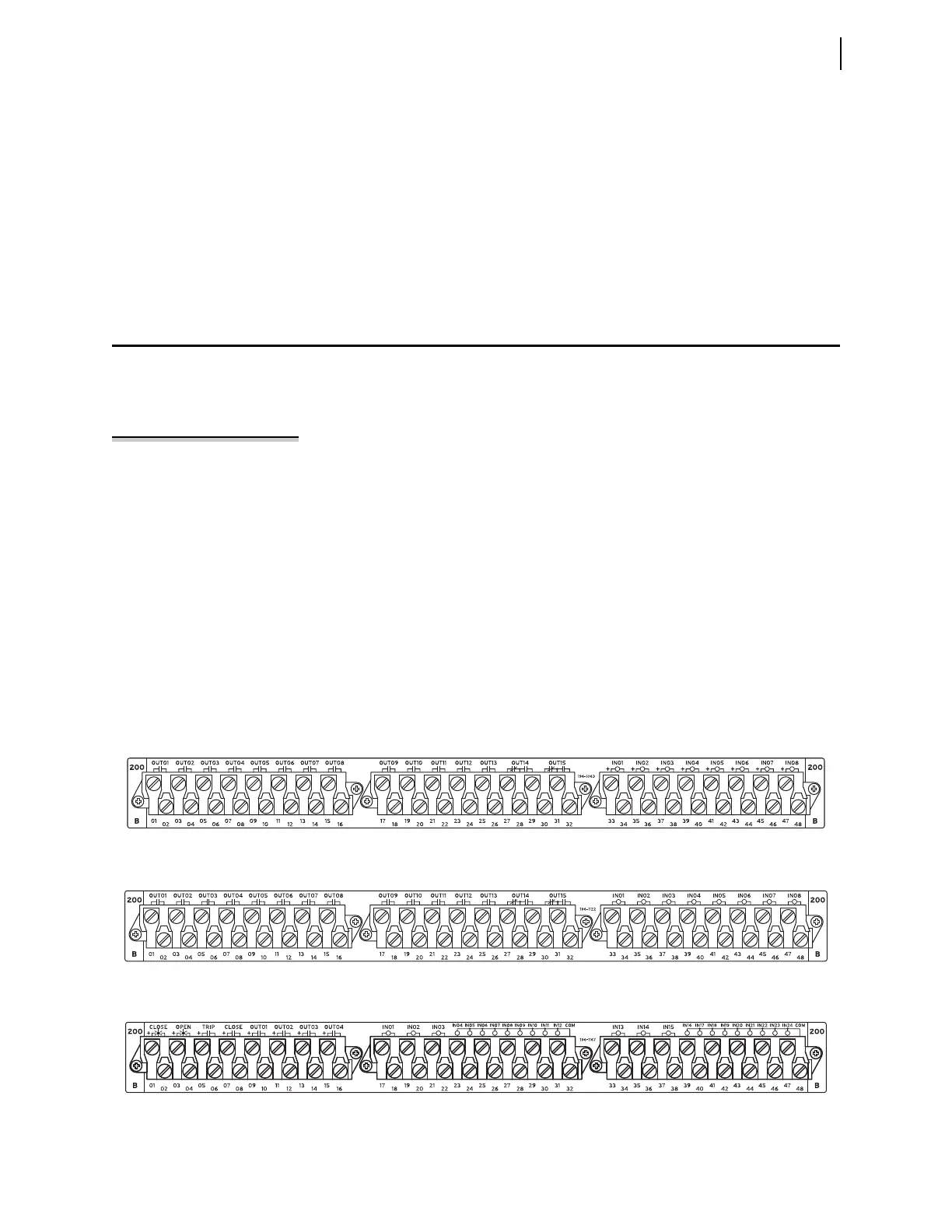
I/O Interface Boards
You can choose among eight input/output interface boards for the I/O slots of the
4U and 5U chassis. These I/O interface boards are in addition to the main board
I/O described in Main Board I/O on page 2.11. The I/O interface boards are
INT1, INT2, INT3, INT4, INT5, INT6, INT7, and INT8. Figure 2.10.
Figure 2.11, Figure 2.12, Figure 2.13, Figure 2.14, Figure 2.15, Figure 2.16, and
Figure 2.17 show the rear screw-terminal connectors associated with these inter-
face boards.
Figure 2.10 INT1 I/O Interface Board
Figure 2.11 INT2 I/O Interface Board
Figure 2.12 INT3 I/O Interface Board