2.34
SEL-421 Relay Instruction Manual Date Code 20171021
Installation
Connection
The SEL-421 accepts dc power input for all three power supply models. The
48–125 Vdc supply also accepts 110–120 Vac; the 125–250 Vdc supply also
accepts 110–240 Vac. When connecting a dc power source, you must connect the
source with the proper polarity, as indicated by the + (Terminal #Z29) and
– (Terminal #Z30) symbols on the power terminals. When connecting to an ac
power source, the + Terminal #Z29 is hot (H), and the – Terminal #Z30 is neutral
(N).
Each model of the SEL-421 internal power supply exhibits low power consump-
tion and a wide input voltage tolerance. For more information on the power sup-
plies, see Power Supply on page 1.14.
Monitor Connections (DC Battery)
The SEL-421 monitors two dc battery systems. For information on the battery
monitoring function, see Station DC Battery System Monitor Specifications on
page 1.19.
NOTE: The combined voltages
applied to the POWER and MONITOR
terminals must not exceed 600 V (rms
or dc).
Connect the positive lead of Battery System 1 to Terminal #Z25 and the negative
lead of Battery System 1 to Terminal #Z26. (Usually Battery System 1 is also
connected to the rear-panel POWER input terminals.) For Battery System 2, con-
nect the positive lead to Terminal #Z27, and the negative lead to Terminal #Z28.
Secondary Circuit Connections
The SEL-421 has two sets of three-phase current inputs and two sets of three-
phase voltage inputs. Secondary Circuits on page 2.5 describes these inputs in
detail. The alert symbol and the word DANGER on the rear panel indicate that you
should use all safety precautions when connecting secondary circuits to these ter-
minals.
To verify these connections, use SEL-421 metering (see Examining Metering
Quantities on page 3.35 in the SEL-400 Series Relays Instruction Manual). You
can also review metering data in an event report that results when you issue the
TRIGGER command (see Triggering Data Captures and Event Reports on
page 9.6 in the SEL-400 Series Relays Instruction Manual).
Fixed Terminal Blocks
Connect the secondary circuits to the Z terminal blocks on the relay rear panel.
Note the polarity dots above the odd-numbered terminals #Z01, #Z03, #Z05, #Z07,
#Z09, and #Z11 for CT inputs. Similar polarity dots are above the odd-numbered
terminals #Z13, #Z15, #Z17, #Z19, #Z21, and #Z23 for PT inputs.
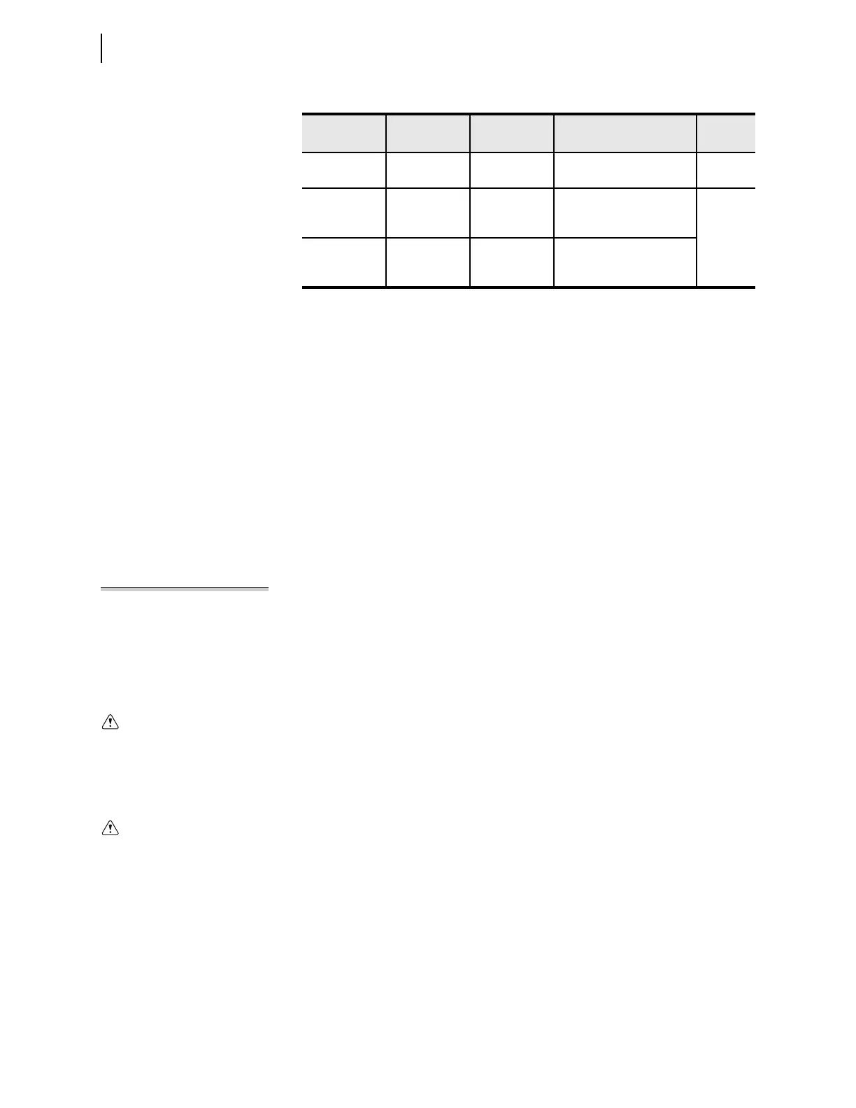
Table 2.11 Fuse Requirements for the Power Supply
Rated Voltage
Operational
Voltage Range
Fuse F1 Fuse Description
Model
Number
24–48 Vdc 18–60 Vdc T5.0AH250V 5x20 mm, time-lag, 5.0 A,
high break capacity, 250 V
042142 or
042152
48–125 Vdc,
110–120 Vac
38–140 Vdc or
85–140 Vac
(30–120 Hz)
T3.15AH250V 5x20 mm, time-lag, 3.15 A,
high break capacity, 250 V
042144 or
042154 or
042146 or
042156
125–250 Vdc,
110–240 Vac
85–300 Vdc or
85–264 Vac
(30–120 Hz)
T3.15AH250V 5x20 mm, time-lag, 3.15 A,
high break capacity, 250 V
Relay misoperation can result from
applying anything other than speci-
fied secondary voltages and currents.
Before making any secondary circuit
connections, check the nominal volt-
age and nominal current specified on
the rear-panel nameplate.
Contact with instrument terminals
can cause electrical shock that can
result in injury or death.