5.100
SEL-421 Relay Instruction Manual Date Code 20171021
Protection Functions
Inverse-Time Overcurrent Elements
NOTE: In the SEL-421, the time-
overcurrent elements are not
directionally controlled in the internal
logic. Directional control may be
achieved through the use of torque
control settings, as shown in
Section 6: Protection Applications
Examples
. Also refer to
Directionality
on page 5.46
.
Each time-overcurrent element has a torque control SELOGIC equation 51SkTC
(k = 1–3) that enables the element when the equation evaluates to logical 1, and
disables the element when the equation evaluates to logical 0. See Figure 5.66 for
a logic diagram of the time-overcurrent elements, including the torque control input.
The enable setting (E51S) controls how many time-overcurrent elements are
available. For example, if E51S := 1, only 51S1 is processed. The remaining
time-overcurrent elements 51Sk (k = 2–3) are defeated, and the output Relay
Word bits are forced to logical 0.
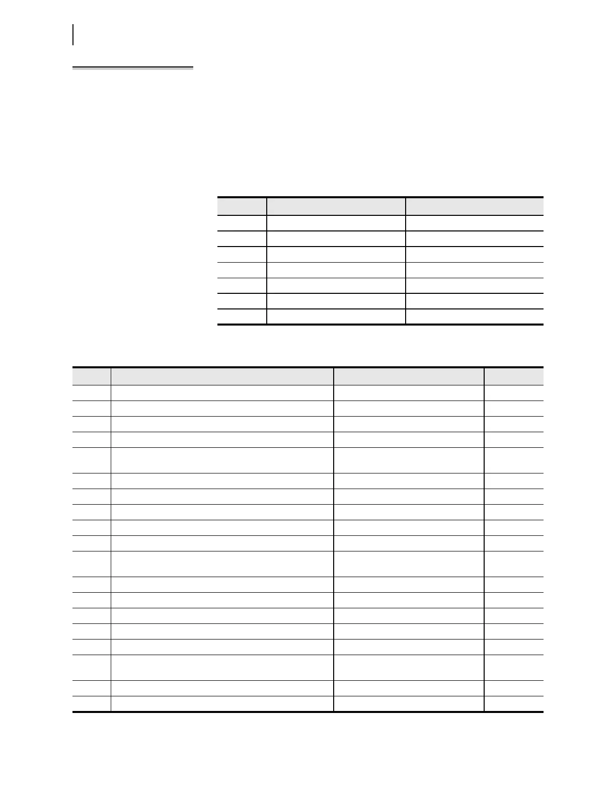
Table 5.61 Selectable Current Quantities
Quantity
a
a
Parameter
n
is L for Line, 1 for BK 1, and 2 for BK 2.
Description Analog Quantities
IAn A-Phase LIAFIM, B1IAFIM, B2IAFIM
IBn B-Phase LIBFIM, B1IBFIM, B2IBFIM
ICn C-Phase LICFIM, B1ICFIM, B2ICFIM
IMAXn Maximum Phase N/A
I1L Line positive-sequence current LI1FIM
3I2L Line negative-sequence current L3I2FIM
3I0n Zero-sequence current LIGFIM, B1IGFIM, B2IGFIM
Table 5.62 Selectable Inverse-Time Overcurrent Settings
Setting
a
a
Parameter
n
is L for Line, 1 for BK1, and 2 for BK2.
Prompt Range Default (5 A)
E51S Selectable Inverse-Time Overcurrent Element N, 1–3 1
51S1O Operating Quantity Element 1 IAn, IBn, ICn, IMAXn, I1L, 3I2L, 3I0n 3I0L
51S1P 51S1 O/C Pickup Element 1 (A) (0.05–3.2) • I
NOM
0.75
51S1C 51S1 Inverse-Time O/C Curve Element 1 U1–U5, C1–C5 U3
51S1TD 51S1 Inverse-Time O/C Time-Dial Element 1 0.50–15.00 (Ux)
b
0.05–1.00 (Cx)
b
b
Parameter
x
is a number from 1—5 indicating the operating curve (see
Figure 5.77
through
Figure 5.86
).
1.0
51S1RS 51S1 Inverse-Time O/C Electromechanical Reset Element 1 Y, N N
51S1TC 51S1 Inverse-Time O/C Torque Control Element 1 SEL
OGIC Equation 32GF
51S2O Operating Quantity Element 2 IAn, IBn, ICn, IMAXn, I1L, 3I2L, 3I0n 3I2L
51S2P 51S2 O/C Pickup Element 2 (A) (0.05–3.2) • I
NOM
5.00
51S2C 51S2 Inverse-Time O/C Curve Element 2 U1–U5, C1–C5 U3
51S2TD 51S2 Inverse-Time O/C Time-Dial Element 2 0.50–15.00 (Ux)
b
0.05–1.00 (Cx)
b
1
51S2RS 51S2 Inverse-Time O/C Electromechanical Reset Element 2 Y, N N
51S2TC 51S2 Inverse-Time O/C Torque Control Element 2 SEL
OGIC Equation 32QF
51S3O Operating Quantity Element 3 IAn, IBn, ICn, IMAXn, I1L, 3I2L, 3I0n IMAXL
51S3P 51S3 O/C Pickup Element 3 (A) OFF, (0.05–3.2) • I
NOM
5.00
51S3C 51S3 Inverse-Time O/C Curve Element 3 U1–U5, C1–C5 U3
51S3TD 51S3 Inverse-Time O/C Time-Dial Element 3 0.50–15.00 (Ux)
b
0.05–1.00 (Cx)
b
1
51S3RS 51S3 Inverse-Time O/C Electromechanical Reset Element 3 Y, N N
51S3TC 51S3 Inverse-Time O/C Torque Control Element 3 SEL
OGIC Equation Z2P