2.44
SEL-421 Relay Instruction Manual Date Code 20171021
Installation
Connection
Commissioning
In TiDL applications, the relay receives currents from a remote module. You
must set the nominal current input of the relay to either 1 A or 5 A. Many settings
and ranges of settings depend on the nominal current. Use the CFG CTNOM
command to set the nominal current value. At Access Level 2, issue a CFG
CTNOM 1 command to set the relay to 1 A values or use the CFG CTNOM 5
command to set it to 5 A values. This command is only available in relays that
support TiDL technology. Note that after issuing this command, the relay settings
are forced to their default values and the relay turns off and back on again to
reinitialize the settings. The relay defaults to 5 A nominal, so only use this com-
mand if you are switching to a 1 A setting (see Section 14: ASCII Command Ref-
erence in the SEL-400 Series Relays Instruction Manual for more information).
The SEL-2245-42 AC Analog Input Module also sets its internal calculations
based on this command. The relay internally transmits this data to the Axion
modules and adjusts the scaling in the appropriate Axion module when this com-
mand is used.
In addition to the CT nominal values, TiDL relays also require that the nominal
frequency be set by issuing the CFG NFREQ command. At Access Level 2,
issue a CFG NFREQ 60 command to set the relay to 60 Hz nominal or issue a
CFG NFREQ 50 command to set the relay to 50 Hz nominal. This command
changes the NFREQ setting and restarts the relay, and it is only available in TiDL
relays. The relay defaults to 60 Hz. This command should be issued after the
CFG CTNOM command but before settings are sent to the relay.
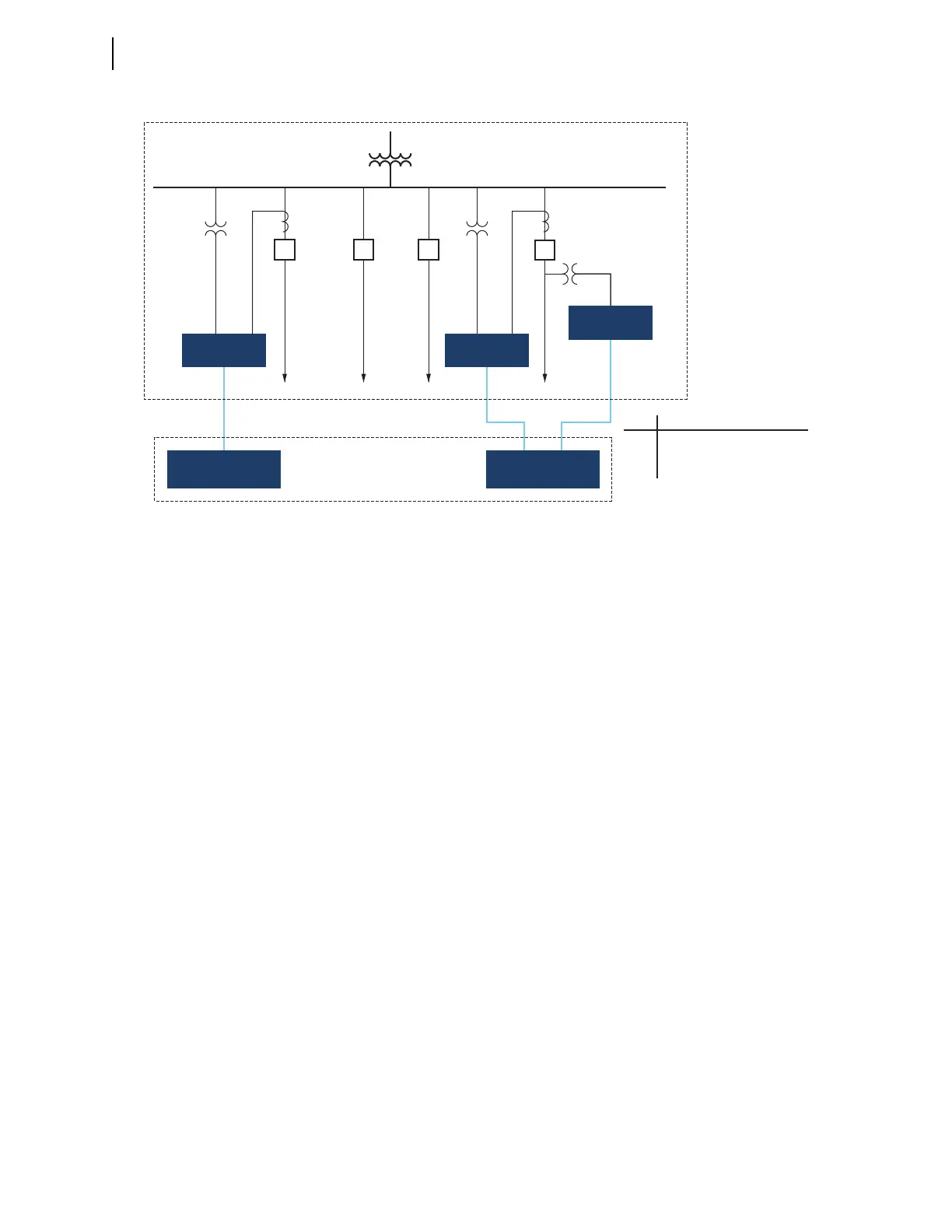
The TiDL system uses a commissioning feature to identify that the connected
remote Axion nodes meet the requirements of the supported topologies for the
applied relay. These topologies are a balance between copper reduction and num-
ber of nodes. The nodes must be connected in one of the supported topologies so
that the relay will map the voltages and currents accordingly.
Figure 2.45 Topology 3
VAY,
VBY,
VCY
VAY,
VBY,
VCY
VAZ,
VBZ,
VCZ
IAW, IBW, ICW IAW, IBW, ICW
Port
6A
6B
Analogs
IAW, IBW, ICW, VAY, VBY, VCY
IAX, IBX, ICX, VAZ, VBZ, VCZ
(optional)
Feeder 1 Feeder 2 Feeder 3
Feeder 4
SEL Relay SEL Relay
SEL Axion SEL Axion
SEL Axion
Control House
Substation Yard