6.156
SEL-421 Relay Instruction Manual Date Code 20171021
Protection Applications Examples
Circuit Breaker Failure Application Examples
Relay Configuration
Enable Scheme 1 circuit breaker failure protection for Circuit Breaker BK1.
EBFL1 := 1. Breaker 1 Failure Logic (N, 1, 2, Y1, Y2)
Circuit Breaker 1 Failure Logic
Phase Current Level Detector
NOTE: This is one method for
calculating setting 50FP1. Use your
company practices and policies for
determining the pickup setting for
your particular application.
Set the phase current level detector equal to 120 percent of the maximum load
current I
load
. Check that this setting is less than the minimum fault current (
fault) with minimum generation. Circuit breaker failure protection for faults
involving ground (SLG and G faults) is covered in this application example by
no current/residual current circuit breaker failure protection (see Residual Cur-
rent Circuit Breaker Failure Protection on page 6.158). This settings philosophy
provides security for the circuit breaker failure protection. For this power system,
the maximum load current is 4.95 A secondary and the minimum fault current
is 13.0 A secondary.
50FP1 = 120% • I
load
= 120% • 4.95 A = 5.94 A
50FP1 := 5.94. Phase Fault Current Pickup—BK1 (0.50–50 A secondary)
Circuit Breaker Failure Protection Time Delay
The recommended setting for BFPU1 (Breaker Failure Time Delay—BK1) is the
sum of the following (see Figure 6.43):
➤ Maximum circuit breaker operating time
➤ 50FA1 maximum dropout time
➤ Safety margin
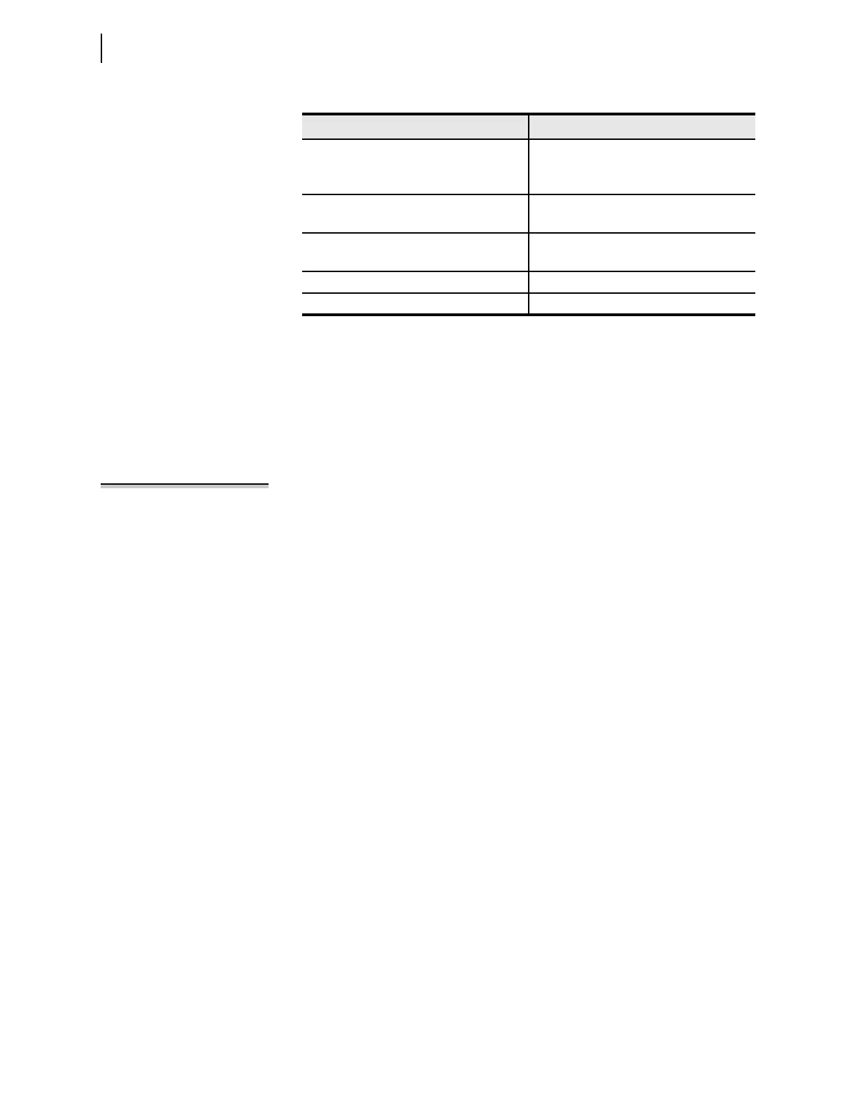
Table 6.41 Secondary Quantities
Parameter Value
Line impedances
Z
1L
Z
0L
1.95 84° secondary
6.2 81.5° secondary
Source S impedances
Z
1S
= Z
0S
2.5 86° secondary
Source R impedances
Z
1R
= Z
0R
2.5 86° secondary
Nominal frequency (f
NOM
)60 Hz
Maximum operating current load (I
load
) 4.95 A secondary