15.31
Date Code 20171006 Instruction Manual SEL-400 Series Relays
Communications Interfaces
SEL M
IRRORED BITS Communication
SEL MIRRORED BITS Communication
With SEL-patented MIRRORED BITS communications protocol, protective relays
and other devices can directly exchange information quickly, securely, and with
minimal cost. Use M
IRRORED BITS communications for remote control, remote
sensing, or communications-assisted protection schemes such as POTT and DCB.
SEL products support several variations of M
IRRORED BITS communications pro-
tocols. Through port settings, you can set the relay for compatible operation with
SEL-300 series relays, the SEL-2505 or SEL-2506 Remote I/O Modules, and the
SEL-2100 Protection Logic Processors. These devices use M
IRRORED BITS com-
munications to exchange the states of eight logic bits. You can also use settings to
select extensions of the M
IRRORED BITS communications protocols, available
only in SEL-400 series relays, to exchange analog values, synchronize clocks,
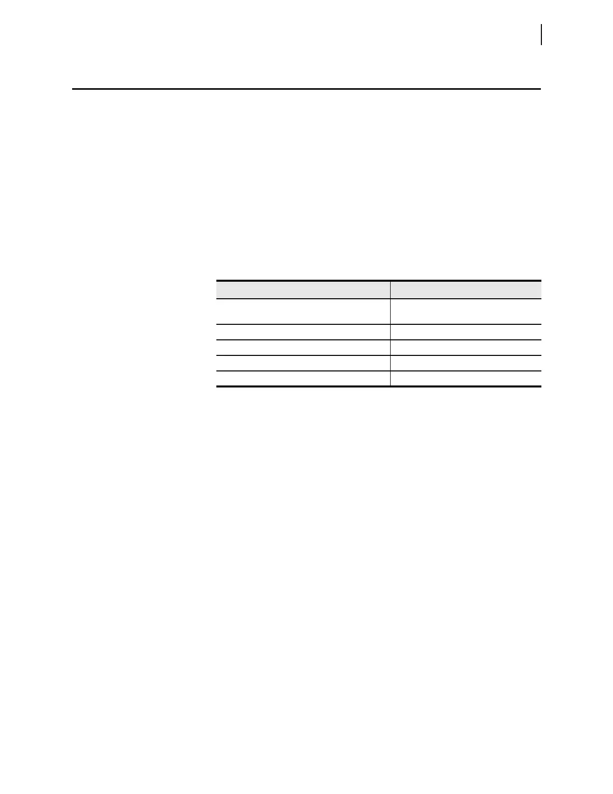
and engage in virtual terminal dialogs. Table 15.23 summarizes M
IRRORED BITS
communications features.
Communications Channels and Logical Data Channels
The relay supports two MIRRORED BITS communications channels, designated A
and B. Use the port setting PROTO to assign one of the M
IRRORED BITS commu-
nications channels to a serial port: PROTO := MBA or MBGA for M
IRRORED
B
ITS communications Channel A or PROTO := MBB or MBGB for MIRRORED
B
ITS communications Channel B.
Transmitted bits include TMB1A–TMB8A and TMB1B–TMB8B. The last letter
(A or B) designates with which channel the bits are associated. These bits are
controlled by SEL
OGIC control equations. Received bits include RMB1A–
RMB8A and RMB1B–RMB8B. You can use received bits as arguments in
SEL
OGIC control equations. The channel status bits are ROKA, RBADA,
CBADA, LBOKA, ROKB, RBADB, CBADB, LBOKB, DOKA, ANOKA,
DOKB, and ANOKB. You can also use these bits as arguments in SEL
OGIC con-
trol equations. Use the COM command for additional channel status information.
Within each M
IRRORED BITS communications message for a given channel (A or
B), there are eight logical data channels (1–8). In operation compatible with other
SEL products, you can use the eight logical data channels for TMB1–TMB8. If
you use fewer than eight transmit bits, Data Channel 8 is reserved to support data
framing and time synchronization features. You can assign the eight logical data
channels as follows:
Ta b l e 1 5. 23 M IRRORED BITS Communications Features
Feature Compatibility
Transmit and receive logic bits SEL-300 series relays, SEL-2505, SEL-2506,
SEL-2100, SEL-400 series relays
Transmit and receive analog values SEL-400 series relays
Synchronize time SEL-400 series relays
Send and receive virtual serial port characters SEL-400 series relays
Support synchronous communications channel SEL-400 series relays