6.157
Date Code 20171021 Instruction Manual SEL-421 Relay
Protection Applications Examples
Circuit Breaker Failure Application Examples
To maintain system stability, the relay must clear the fault within the total clear-
ing time. Use the maximum operating time of the local and remote circuit break-
ers. The maximum operating time of the circuit breaker, t
l-bk
, is 3 cycles for this
example. Also, use the maximum dropout time for Relay Word bit 50FA1; the
maximum dropout time of the phase current level detector, t
50r
, is 1 cycle. You
must also include the communications channel time, t
ch
, for remote circuit
breaker tripping.
To determine setting BFPU1, you must find the safety margin, ts. Determine the
safety margin from Figure 6.40:
Equation 6.89
Use the safety margin result from Equation 6.89 to calculate BFPU1:
Equation 6.90
BFPU1 := 10.000. Breaker Failure Time Delay—BK1 (0.000–6000 cycles)
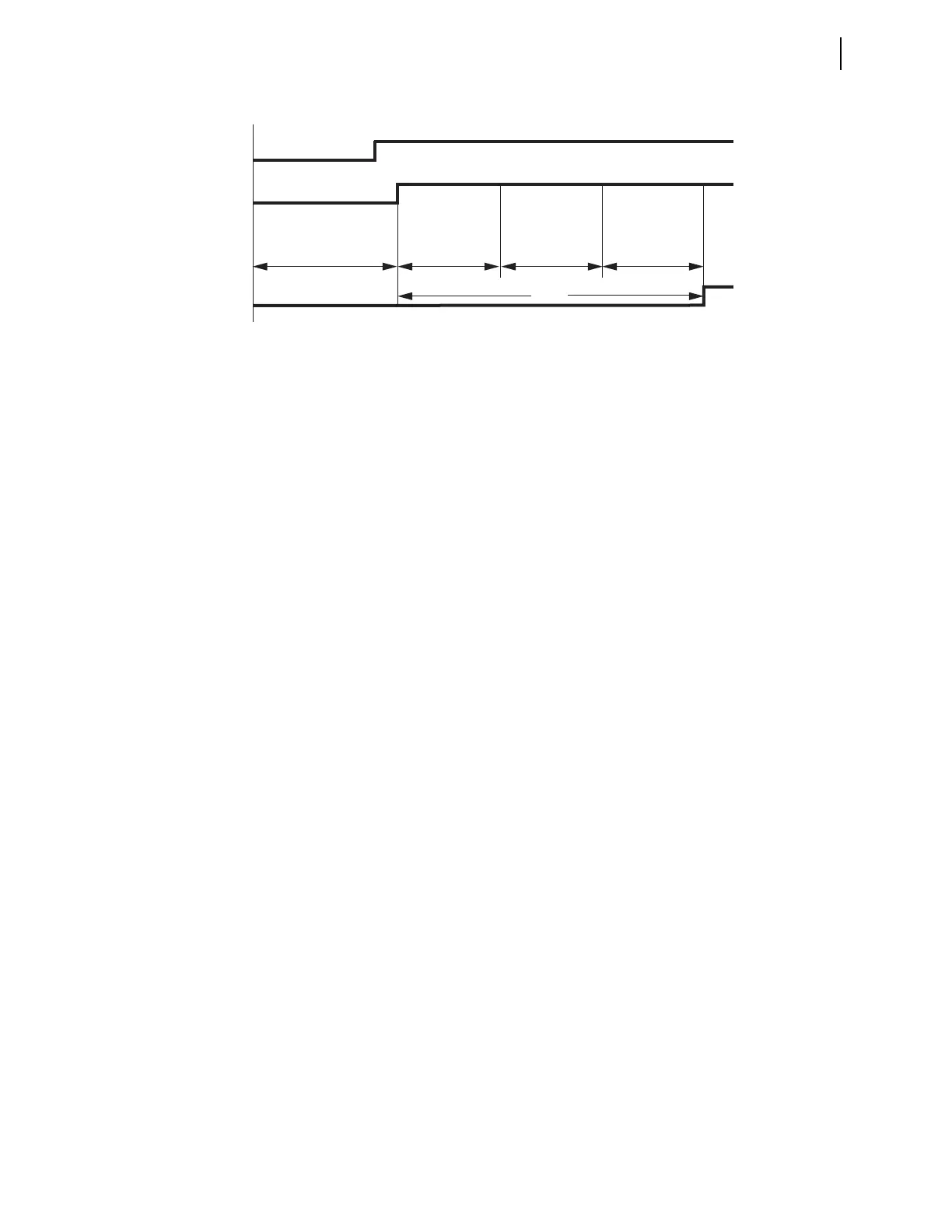
Figure 6.43 Timing Diagram for Setting BFPU1—Scheme 1
Breaker
Operate Time t
l-bk
BFPU1
Line Protection
Maximum Operate Time
Fault Occurs
50FA1
BFI3P1
FBF1
50FA1
Dropout Time, t
50r
Safety
Margin Time, t
s
where:
t
s
= safety margin
t
t
= total clearing time (17 cycles)
t
lr
= line protection maximum operating time (2 cycles)
t
l-bk
= local circuit breaker maximum operating time (3 cycles)
t
50r
= circuit breaker failure overcurrent element 50FA1 maximum
reset time (1 cycle)
t
86
= auxiliary breaker failure relay operating time (1 cycle)
t
ch
= communications channel maximum operating time (1 cycle)
t
r-bk
= remote circuit breaker maximum operating time (3 cycles)
t
s
t
t
t
1r
t
1bk–
t
50r
t
86
t
ch
t
rbk–
+++++–=
17 231113+++++–=
6 cycles=
BFPU1 t
1bk–
t
50r
t
s
++=
316++=
10 cycles=