5.171
Date Code 20171021 Instruction Manual SEL-421 Relay
Protection Functions
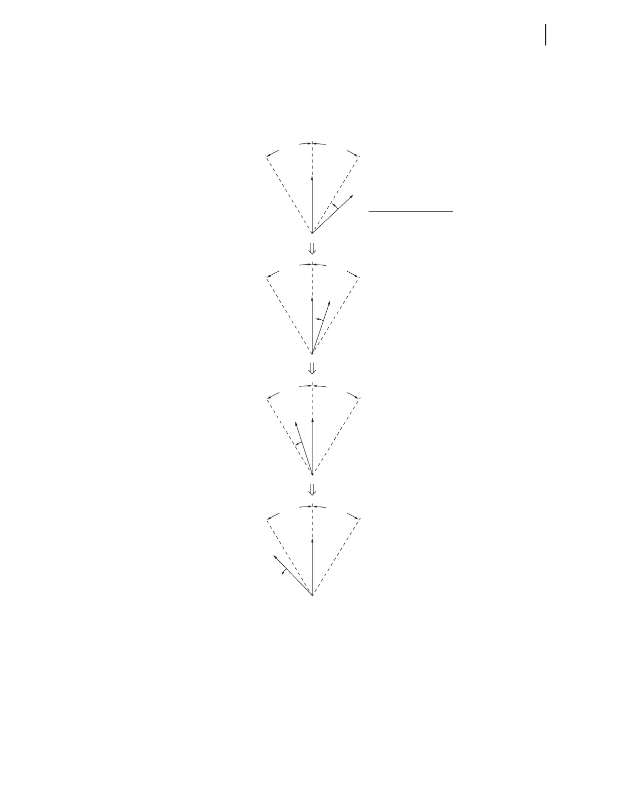
Synchronism Check
V
S1
slips with respect to synchronism-check voltage reference V
P
. The indication
of the rotation arrow on phasor V
S1
(and the time progression down the page)
shows that the system corresponding to V
S1
has a higher system frequency f
S1
than the system corresponding to reference V
P
with system frequency f
P
. The slip
frequency across Circuit Breaker BK1 is f
S1
–f
P
.
Positive Slip Frequency
If the slip frequency is positive, V
S1
is slipping ahead of reference V
P
(the system
corresponding to V
S1
has a higher system frequency than the system correspond-
ing to V
P
; f
S1
> f
P
). Positive slip frequency is the counter-clockwise rotation of
V
S1
with respect to reference V
P
, as shown in Figure 5.129. Relay Word bit
FAST1 asserts to logical 1 (and Relay Word bit SLOW1 deasserts to logical 0) to
indicate this condition.
Figure 5.129 “Slip—No Compensation” Synchronism-Check Element Output
Response
V
P
(a)
(b)
(c)
(d)
V
S1
V
P
V
S1
V
P
V
S1
V
P
V
S1
Slip (asynchronous systems—not paralleled).
Max slip frequency setting 25SFBK1 := OFF
Response of synchronism-check
element outputs (Relay Word Bits):
25W1BK1 = logical 1
25A1BK1 = logical 1
25W1BK1 = logical 1
25A1BK1 = logical 1
25W1BK1 = logical 0
25A1BK1 = logical 0
25W1BK1 = logical 0
25A1BK1 = logical 0
A
N
G
1
B
K
1
A
N
G
1
B
K
1
A
N
G
1
B
K
1
A
N
G
1
B
K
1
A
N
G
1
B
K
1
A
N
G
1
B
K
1
A
N
G
1
B
K
1
A
N
G
1
B
K
1