3.69
Date Code 20171006 Instruction Manual SEL-400 Series Relays
Basic Relay Operations
Operating the Relay Inputs and Outputs
Step 4. Assign a control output for the close bus.
a. In the Main Board Outputs dialog box, click the OUT106 text
box and type the following:
BK1CL #ADDITIONAL BREAKER 1 CLOSE
(The # indicates that a comment follows.)
b. Click or tab to another text box.
QuickSet checks that your entry is valid.
Step 5. Click File > Save to save the new settings in QuickSet.
Step 6. Upload the new settings to the relay.
a. Click File > Send.
QuickSet prompts you for the settings class or instance you want
to send to the relay.
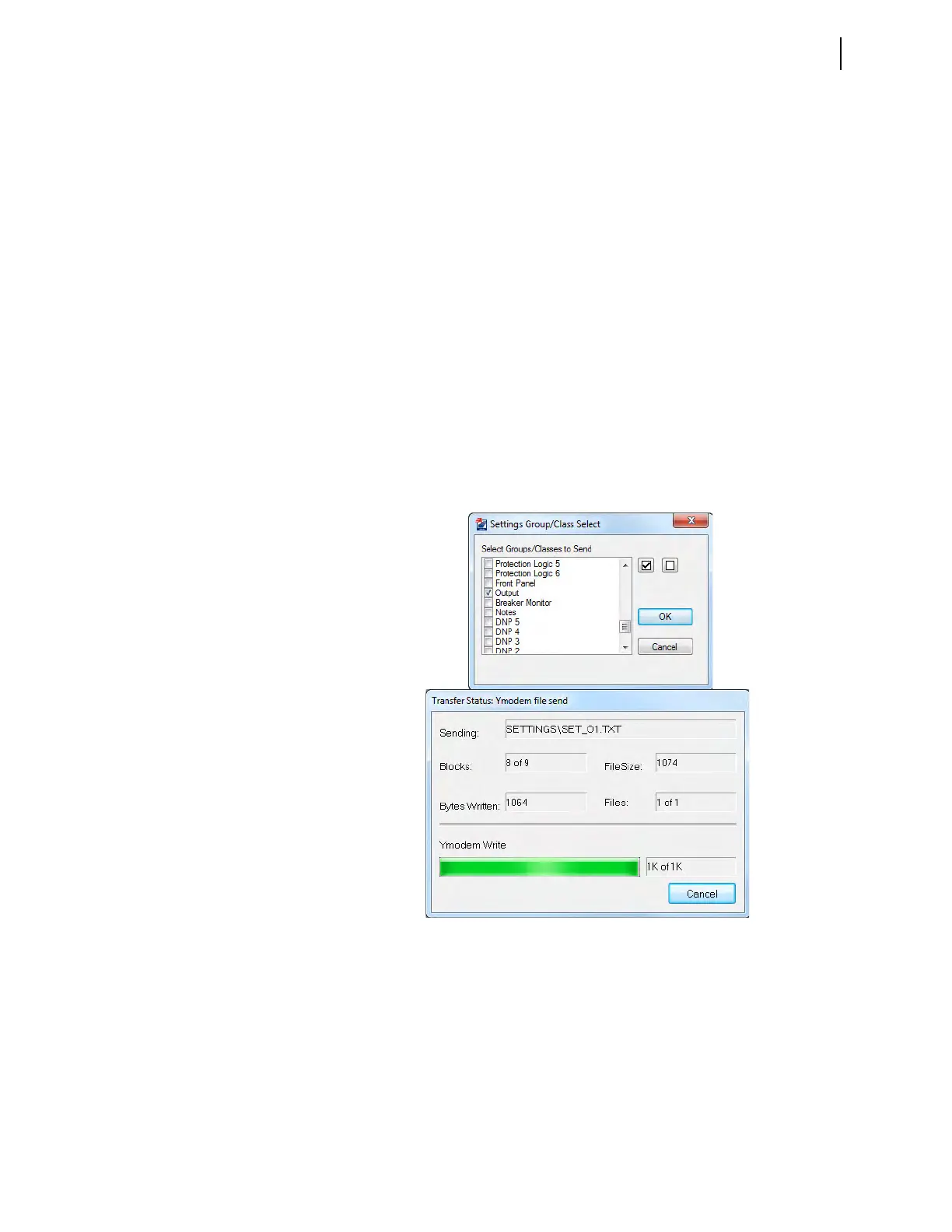
b. Click the check box for Outputs as shown in the first dialog box
shown in Figure 3.62.
c. Click OK.
QuickSet responds with the second dialog box of Figure 3.62.
If you see no error message, the new settings are loaded in the relay.
Control Input Assignment
Most SEL-400 series relays have control inputs on the main board (IN101–IN107),
and on one or more optional I/O interface boards (IN201–IN2xx, IN301–IN3xx,
etc.), if so equipped.
Figure 3.62 Uploading Output Settings to the SEL-451