5.116
SEL-421 Relay Instruction Manual Date Code 20171021
Protection Functions
Over- and Undervoltage Elements
27P
n
D1 (Undervoltage Level 1 Time Delay)
NOTE: If the relay is using a remote
data acquisition system, such as TiDL,
the operating times will be delayed by
1.5 ms. Use caution when setting the
relay coordination times to account
for this added delay.
When the system voltage falls below the undervoltage setting value, the under-
voltage timer starts timing. Set the delay (in cycles) for which the timer must run
before the output asserts.
59O
n
(Overvoltage Element Operating Quantity)
Select from Table 1.70 the desired operating quantity for each voltage terminal.
59P
n
P1 (Overvoltage Level 1 Pickup)
Set pickup values for the voltage values above which you want the Level 1 over-
voltage elements to assert.
59P
n
P2 (Overvoltage Level 2 Pickup)
Set pickup values for the voltage value above which you want the Level 2 over-
voltage elements to assert.
59TC
n
(Overvoltage Torque Control)
Use the torque-control setting to specify conditions under which the overvoltage
elements must be active. There is only one setting for both Level 1 and Level 2
elements. With the default setting equal to 1, both levels are active permanently.
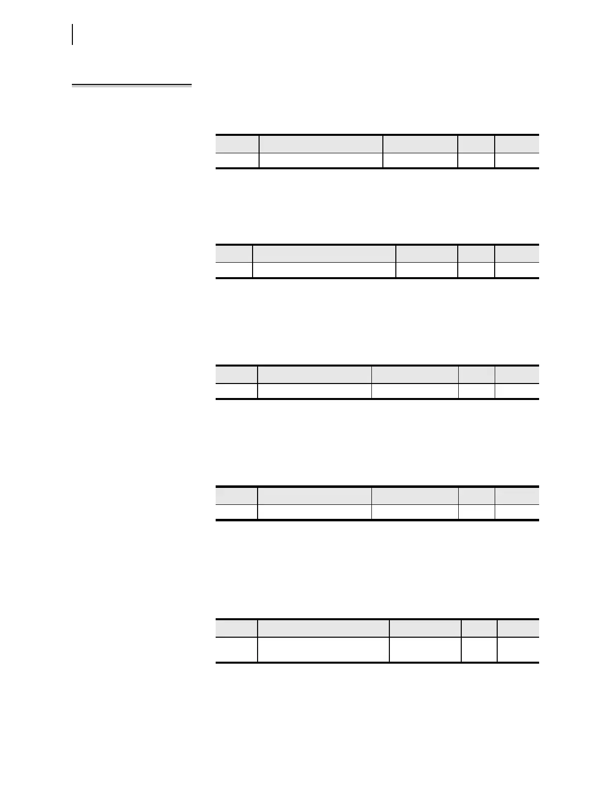
Setting Prompt Range Default Category
27PnD1
a
a
n
= 1–6.
U/V Element n Level 1 Delay 0.00 to 16000 cyc. 10 Group
Setting Prompt Range Default Category
59On
a
a
n
= 1–6.
O/V Element n Operating Quantity See Table 5 .66 V1FIM Group
Setting Prompt Range Default Category
59PnP1
a
a
n
= 1–6.
O/V Element n Level 1 P/U 2.00 to 300 volts, sec. 76 Group
Setting Prompt Range Default Category
59PnP2
a
a
n
= 1–6.
O/V Element n Level 2 P/U 2.00 to 300 volts, sec. 80 Group
Setting Prompt Range Default Category
59TCn
a
a
n
= 1–6.
O/V Element n Torque Control
(SEL
OGIC Equation)
SEL
OGIC Equation 1 Group