5.162
SEL-421 Relay Instruction Manual Date Code 20171021
Protection Functions
Synchronism Check
Supervising Circuit Breaker Closing via Synchronism Check
Use the synchronism-check element outputs to control circuit breaker closing.
Some examples follow (the ellipsis indicates other elements that you can add to
these SEL
OGIC control equations).
Supervising Autoreclosing of Circuit Breaker BK1
3P1CLS := 25A1BK1 OR … Three-Pole BK1 Reclose Supervision
(SEL
OGIC Equation)
Manual Closing of Circuit Breaker BK1
BK1MCL := 25W2BK1 OR … Circuit Breaker BK1 Manual Close
(SEL
OGIC Equation)
PT Connections
Figure 5.122 is an example of connecting PTs to the relay for two circuit break-
ers. The Bus 1 and Bus 2 single-phase voltages are connected to relay voltage
inputs VAZ and VBZ, respectively. They could just as easily have been connected
to any of the other voltage inputs. The voltage connected to voltage input VAZ
(setting SYNCS1 := VAZ; see Figure 5.122) is not necessarily from A-Phase on
Bus 1. Likewise, the voltage connected to voltage input VBZ (setting
SYNCS2 := VBZ; see Figure 5.122) is not necessarily from B-Phase on Bus 2.
The connection can be from any phase-to-neutral or phase-to-phase voltage (as
long as you do not exceed the relay voltage input ratings). Settings in the relay
compensate for any steady-state magnitude or angle difference with respect to a
synchronism-check voltage reference, as discussed next in this example.
Three-phase line voltages are connected to relay voltage inputs VAY, VBY, and
VCY (these voltage inputs are also used for distance elements fault location, loss-
of-potential, load encroachment, and directionality). Only one of these single-
phase voltage inputs is designated for use in synchronism check. In this example,
this voltage input is also designated the synchronism-check voltage reference
(setting SYNCP := VAY; see Figure 5.122). As the synchronism-check voltage
reference, the relay makes all steady-state magnitude and angle adjustments for
the Bus 1 and Bus 2 synchronism check voltages (connected to voltage inputs
FAZ and FBZ, respectively, as discussed in the preceding paragraph) with respect
to this designated reference line voltage, VAY, as discussed later in this example.
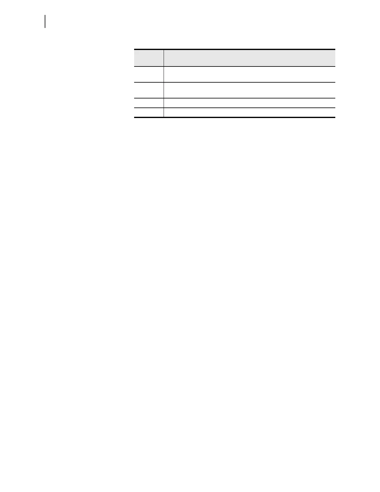
25A1BK2 Same operation as 25W1BK2, except for the restrictive operation (0° closure attempt)
when setting 25SFBK2 OFF and the system is slipping (see Figure 5.130)
25A2BK2 Same operation as 25W2BK2, except for the restrictive operation (0° closure attempt)
when setting 25SFBK2 OFF and the system is slipping (see Figure 5.130)
FAST2 Bus 2 frequency greater than line frequency (f
S2
> f
P
)
SLOW2 Bus 2 frequency less than line frequency (f
S2
< f
P
)
Table 5.81 Synchronism-Check Relay Word Bits (Sheet 2 of 2)
Relay
Word Bit
Description