Maintenance
2138−1/A2
RT-flex50-D
Wärtsilä Switzerland Ltd
1/ 4
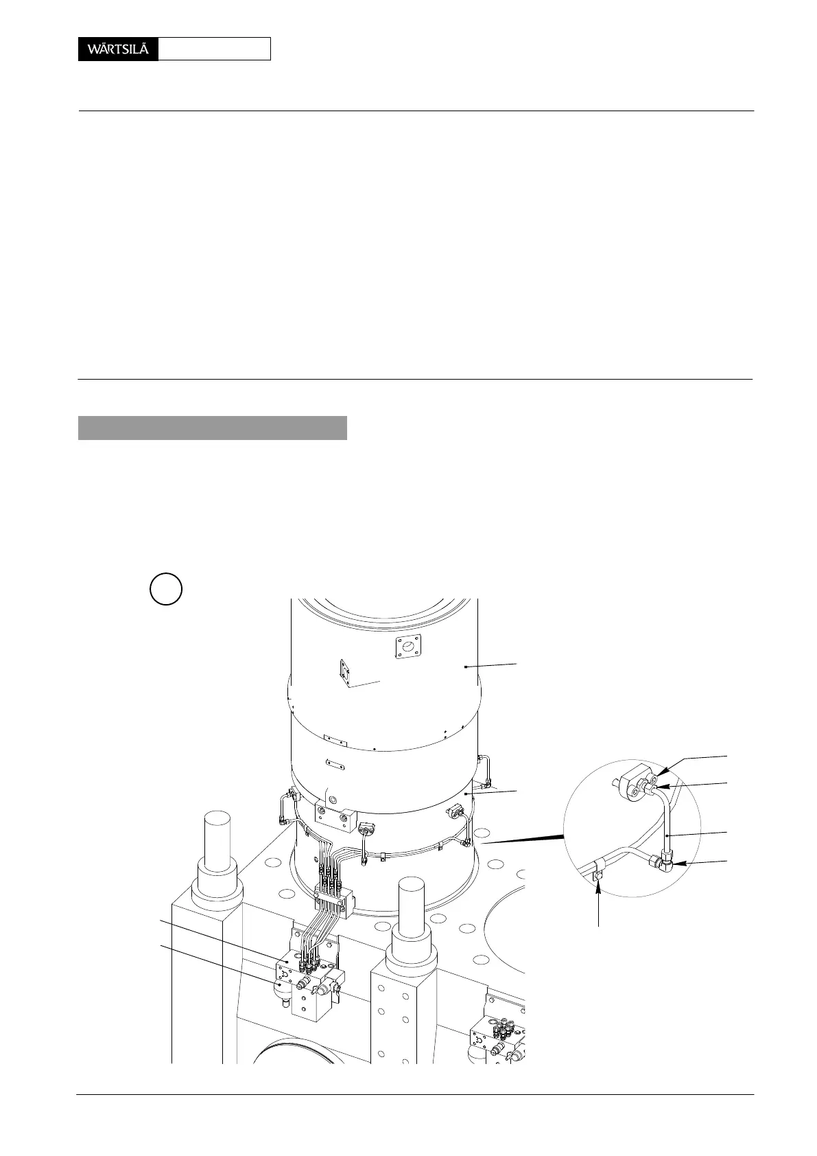
Tool: Key to Illustrations:
1 Tool box 94720c 1 Cylinder liner 13 4/2-way solenoid valve
with fittings for charging 2 Lubricating pump 14 Sink plunger
accumulator 3 Accumulator 15 Pin (tool)
1 HP oil pump 94931 4 Water guide jacket (lower part) 16 Shut-off valve servo oil
1 Hydr. distributor 94934h 5 Lubricating quill (items 6 to 8) 17 Venting valve servo oil
(with pr. gauge 0...25 bar) 6 Nozzle tip 18 Venting valve lube oil
1
Connection nipple (G¼”)
94934i 7 Holder 19 Pipe bracket
1 HP hose 94935 8 Non-return valve
9 Allen screw M10x50
10 Screw-in union
11 Angle union
12 Lubricating oil pipe DF Sealing surface
1. General
If the lubricating quill (items 6 to 8) must be removed with cylinder liner in situ, the
cylinder cooling water must not be drained.
In order to remove a cylinder liner 1 however, it is recommended to remove first all
lubricating quills, whereby the cylinder cooling water must be drained on the
relevant cylinder (see 2708−1 ’Removal of cylinder cover’).
A
2
3
4
1
9
1
1
11
19
WCH00107
ubricating Quill
emoval and Fitting with Pulse Jet Lubricatio
Pulse Jet / 2011