Maintenance2138−1/A2 RT-flex50-D
Wärtsilä Switzerland Ltd
2/ 4
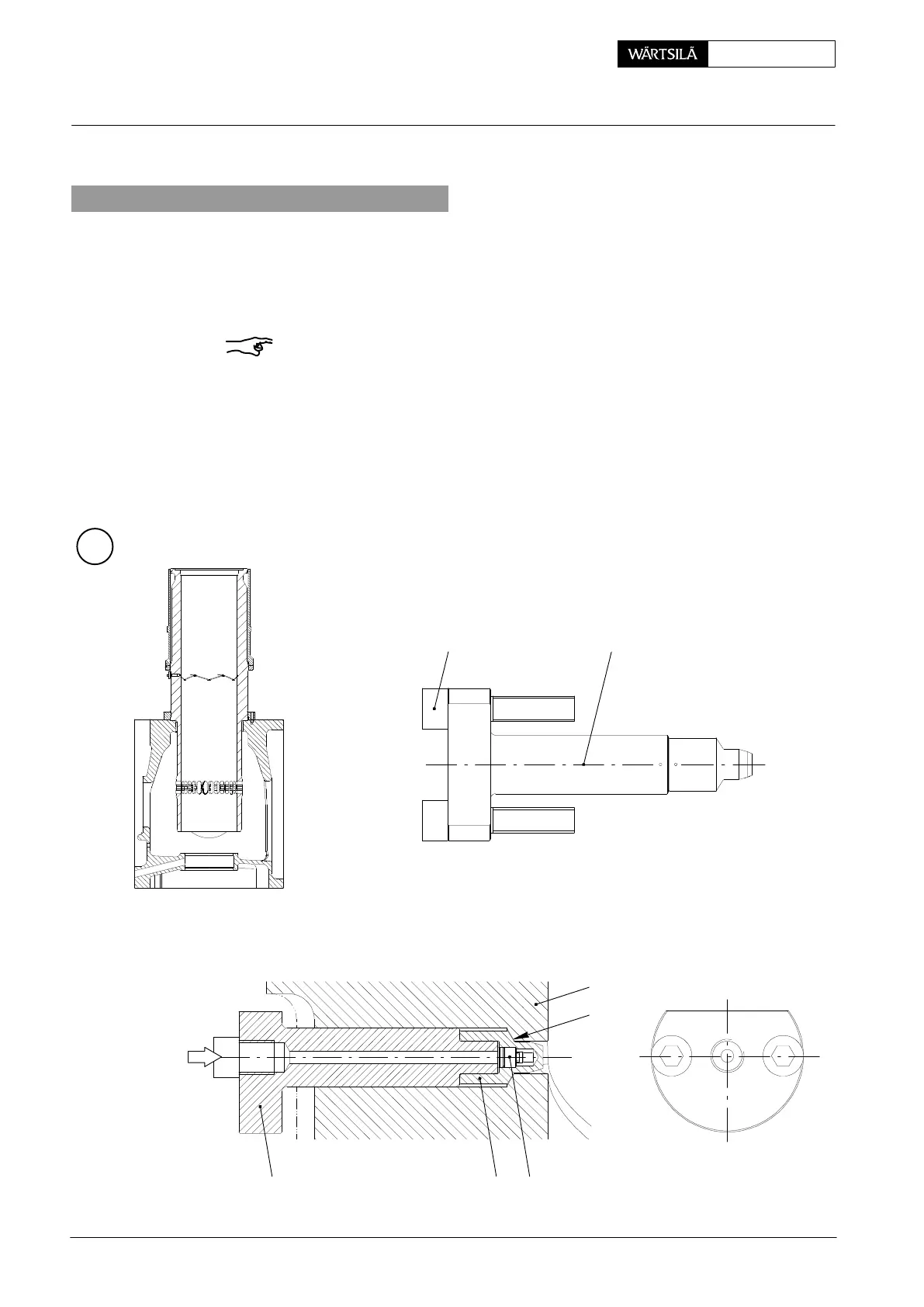
2. Removal and fitting of lubricating quill
⇒ Loosen Allen screws 9, nuts of screw-in union 10 and angle union 11 (Fig. ’A’).
Disconnect lubricating oil pipe 12 and protect it against any damages and en-
tering of dirt.
⇒ Remove lubricating quill.
Remark: The assembly of nozzle tip / nozzle holder is based on the press fit de-
sign. The lubricating quill must be replaced as a whole unit, i.e. nozzle tip 6
with non-return valve 8 inserted and holder 7.
D When refitting the lubricating quill, the sealing surface ’DF’ must be clean and
undamaged, as it seals metallically. Moreover, the proper seat angles in the
cylinder liner (120_) and on the nozzle tip (114_) differs slightly. Therefore, do
not use any gasket between cylinder liner 1 and nozzle tip 6!
D Tighten the oiled Allen screws 9 with a torque of 10 Nm.
B
7
WCH00112
1
DF
68
59
2011 / Pulse Jet
Lubricating Quill with Pulse Jet Lubricatio