Maintenance4103−3/A1 RT-flex50-D
Wärtsilä Switzerland Ltd
4/ 5
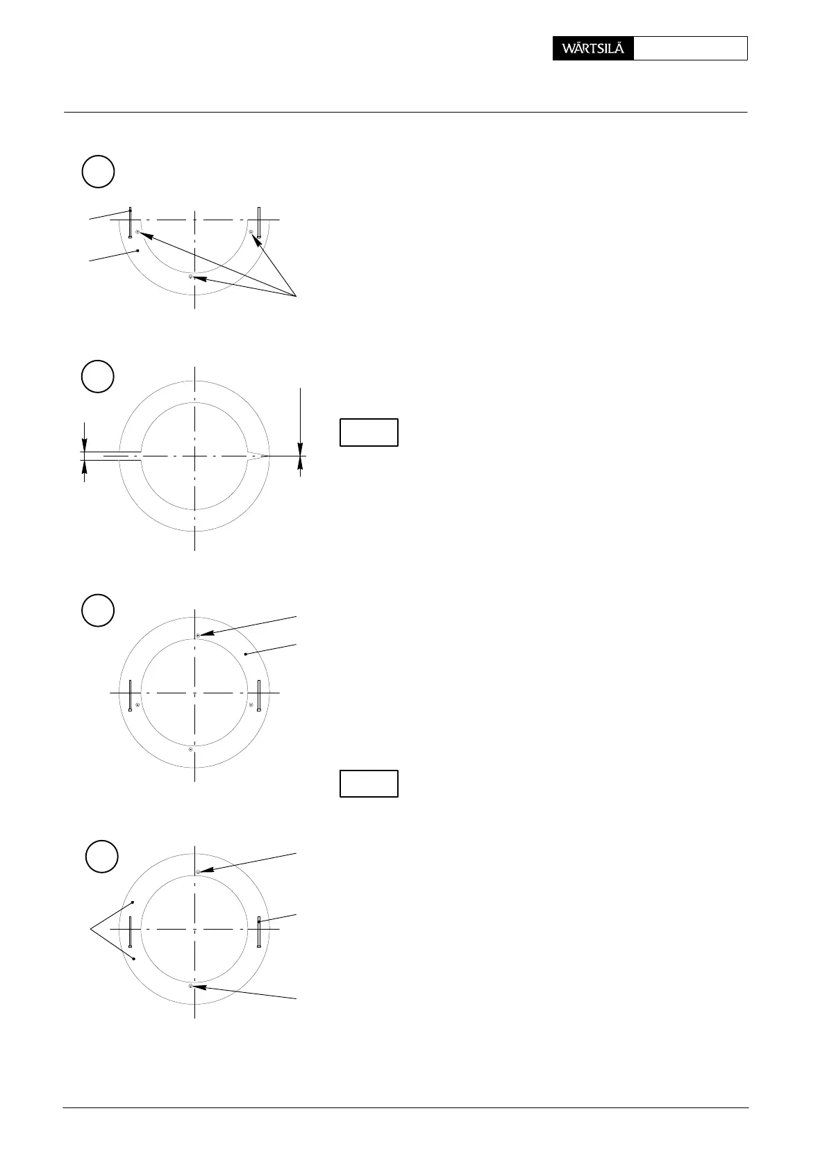
⇒ Turn the gear wheel half to the bottom (Fig. ‘E’) an
place the second gear wheel half, which is also pr
vided with two pre-assembled waisted studs 3, o
the top (Fig. ‘G’).
D Check the correct diameter tolerance by measurin
the size of the gap between both gear wheel halve
For that the gap must be closed on the opposite sid
(Fig. ‘F’).
Gap ‘j’ must be 0.16 mm−0.38 mm. If the dimension
not within the mentioned tolerance, the gear wheel mu
not be assembled, but the center hole has to be given a
appropriate re-machining (see Preparing the assemb
of the gear wheel).
⇒ After measuring, align the gaps between the whe
halves and slightly tighten castle nuts 4 of waiste
studs 3 (Fig. ’C’).
⇒ Also insert a flange screw 6 in the centre of upp
gear wheel half and tighten it temporarily (Fig. ‘G
⇒ Remove flange screws 6 from each end of the low
gear wheel half so that there are now only two flang
screws 6, each of them tightened temporarily in th
centres of the upper and the lower gear wheel ha
(Fig. ‘H’).
CHECK
There must be no clearance on the seating surfaces b
tween the gear wheel and the crankshaft flange − chec
⇒ For fitting the four remaining castle nuts 4 belongin
to waisted studs 3 (Fig. ’C’), apply MOLYKOTE
paste to the threads and the seating surfaces. Tigh
en only the castle nuts treated with MOLYKOT
paste. Use retaining wrench 94412e (Fig. ‘I’) f
holding up the castle nuts opposite which have a
ready been fitted and secured with LOCTITE and
split pin.
⇒ Tighten the four castle nuts of waisted studs 3 cros
wise by means of an impact ring spanner, measurin
and recording the length of the waisted studs b
forehand.
CHECK
E
6
3
1
F
G
j
GAP 0
6
1
H
6
3
6
1
001.167/97
001.166/97
001.166/97
001.166/97
Replacing the Gear Wheel on the Crankshaft
2010