Chapter 4: C4 CMTS General Installation Requirements
STANDARD Revision 1.0 C4® CMTS Release 8.3 User Guide
© 2016 ARRIS Enterprises LLC. All Rights Reserved. 104
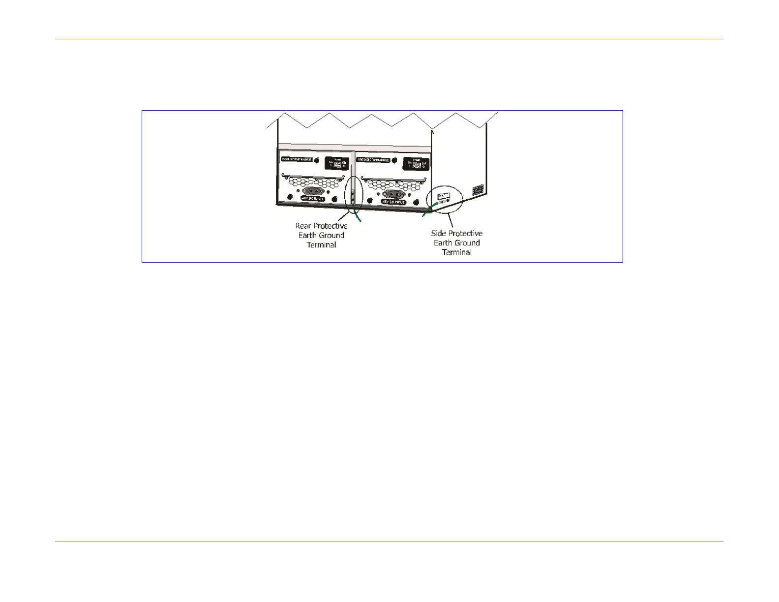
protective earth ground wire to either of these locations before installing the chassis in the rack. See the procedure above
for details on attaching the earth ground cable to the chassis.
Figure 7: Location of Grounding Terminals
Main Hardware Components
The C4 CMTS base system contains the following components:
C4 CMTS chassis
Two Power Conditioning Modules (PCMs) – Power Feeds A & B
Cable Access Module (CAMs) and associated Physical Interface Cards (PICs)
Router Control Module (RCM)
System Control Module and associated PIC
Three Fan Trays which are numbered 0, 1, and 2 (Each Fan Tray contains two fans, marked front and rear.)
Air filter (factory installed)