Chapter 5: C4c CMTS Installation Requirements
STANDARD Revision 1.0 C4® CMTS Release 8.3 User Guide
© 2016 ARRIS Enterprises LLC. All Rights Reserved. 138
The attachment screws for this cable are shipped pre-installed in the chassis. Remove the attachment screws from the
desired ground cable location on the chassis and reattach. The recommended torque for these screws is 10.0 ±0.5 inch-
pounds.
If using telco type racks, be sure to bolt the rack to the floor.
2. Position the C4c CMTS in rack.
3. Install rack bolts to secure the C4c CMTS in position.
4. Secure the loose end of protective earth ground cable to a suitable protective earth ground termination point within
the building installation. If attaching this cable to the frame, ensure that the attachment point is bare metal and that
the frame is bonded to a suitable protective earth ground.
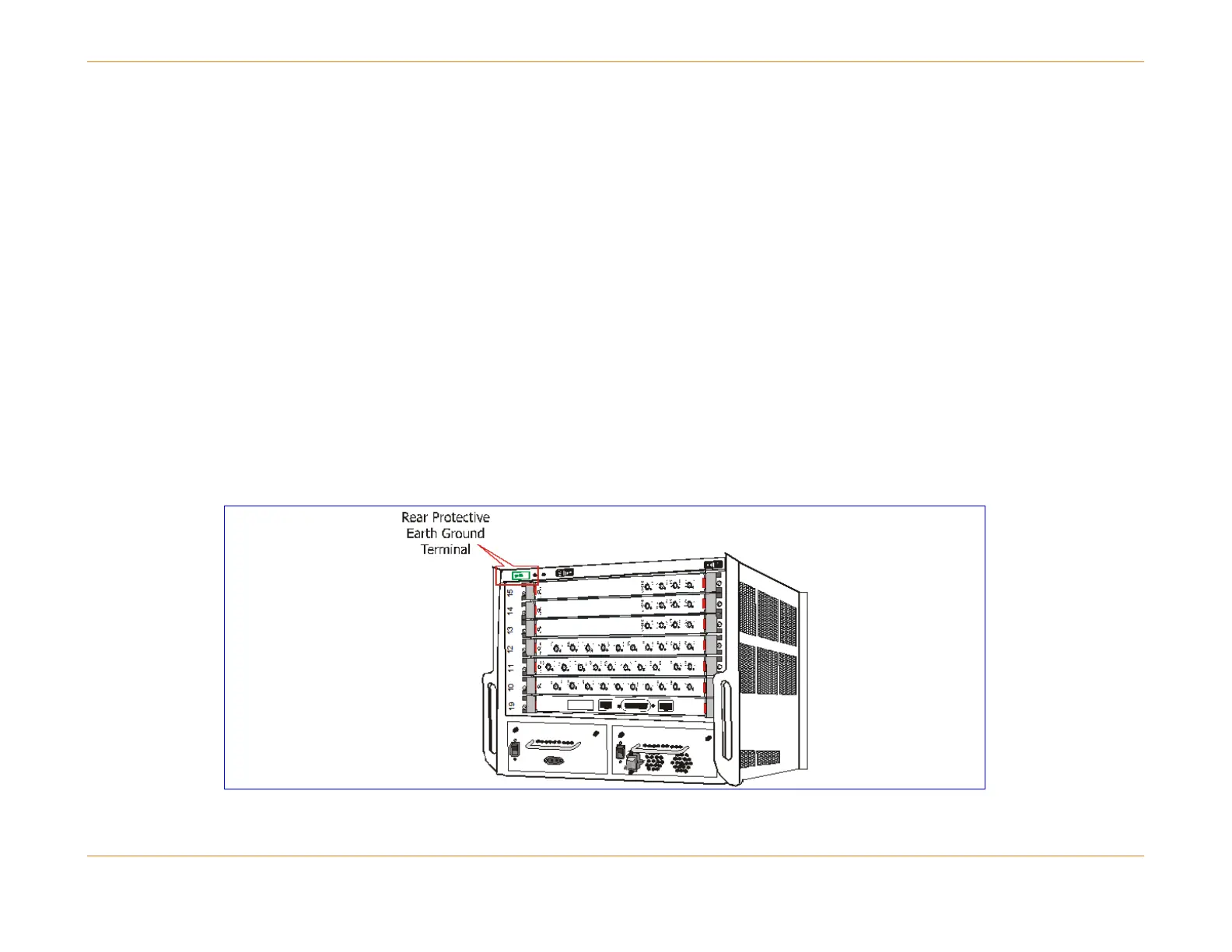
Grounding the Chassis
The C4c CMTS chassis must be properly connected to protective earth ground for safety compliance. You can connect the
protective earth ground wire on the front of the chassis. Install the chassis termination end of the protective earth ground
wire to this location before installing the chassis in the rack. See the procedure above for details on attaching the earth
ground cable to the chassis.
Figure 25: Location of Grounding Terminals