Chapter 5: C4c CMTS Installation Requirements
STANDARD Revision 1.0 C4® CMTS Release 8.3 User Guide
© 2016 ARRIS Enterprises LLC. All Rights Reserved. 146
Installation Diagram
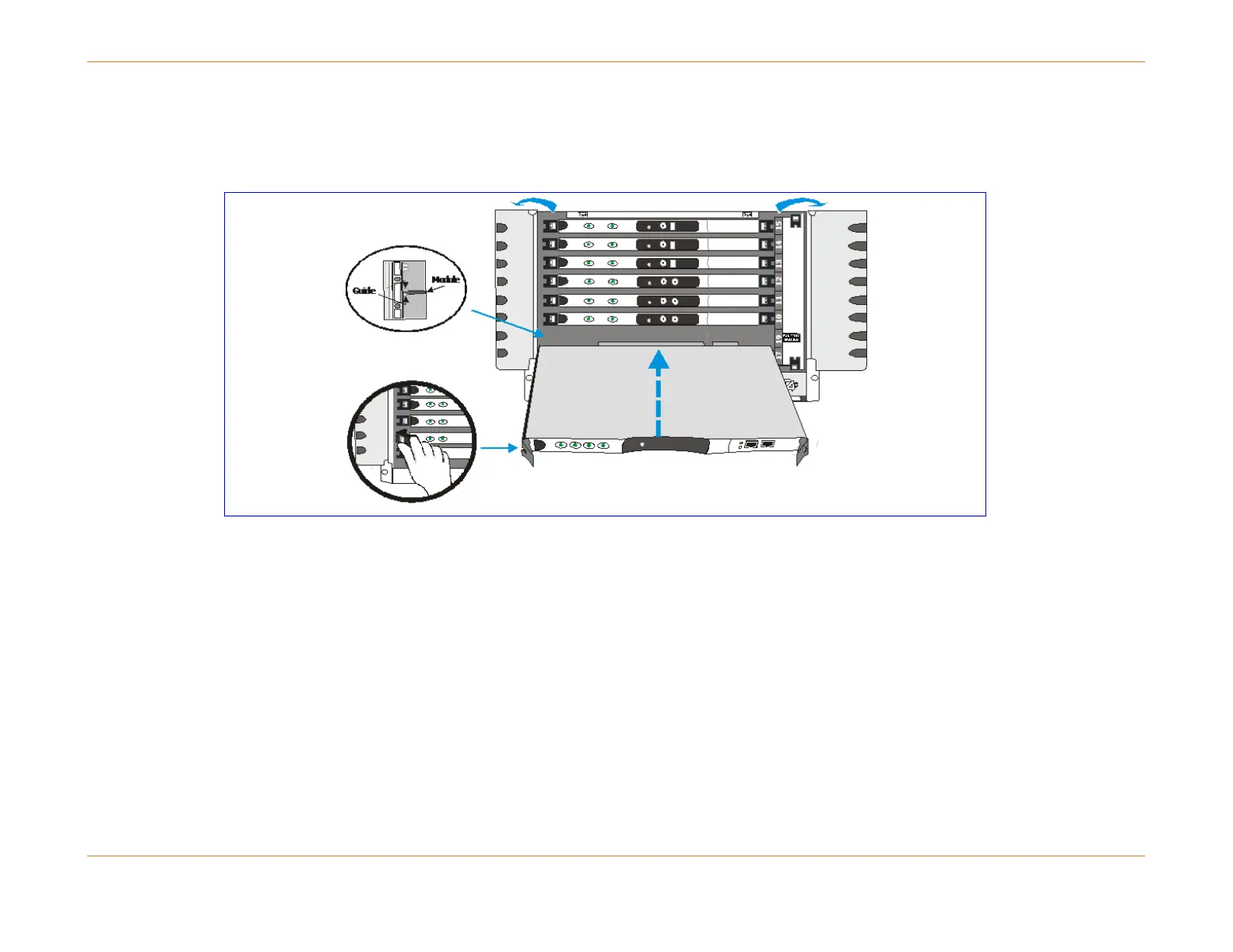
Although the figure below shows the SCM, the side ejector lever is the same for all modules and PICs.
Figure 29: Installing the System Control Module
Ejector Levers
The figure below illustrates the ejector lever mechanism on the module faceplates. Once installed the module is locked in
place. The red button in each lever must be pushed before the ejector levers can be operated to release the module.
Always operate both (left and right) ejector levers at the same time when seating or releasing the module.