GE
P
ART NUMBER FN091065, REVISION 2 VS5 N AND VS6 N SERVICE MANUAL
8-124 Section 8-6 - Lower Section Components Replacement Procedures
PRELIMINARY
already registered in the Hard Disk. Only qualified personnel should perform these tasks.
NOTE: When performing the following installation procedure steps, it may be helpful to review the appropriate
movie clips previously referenced in the Hard Disk Removal Procedure.
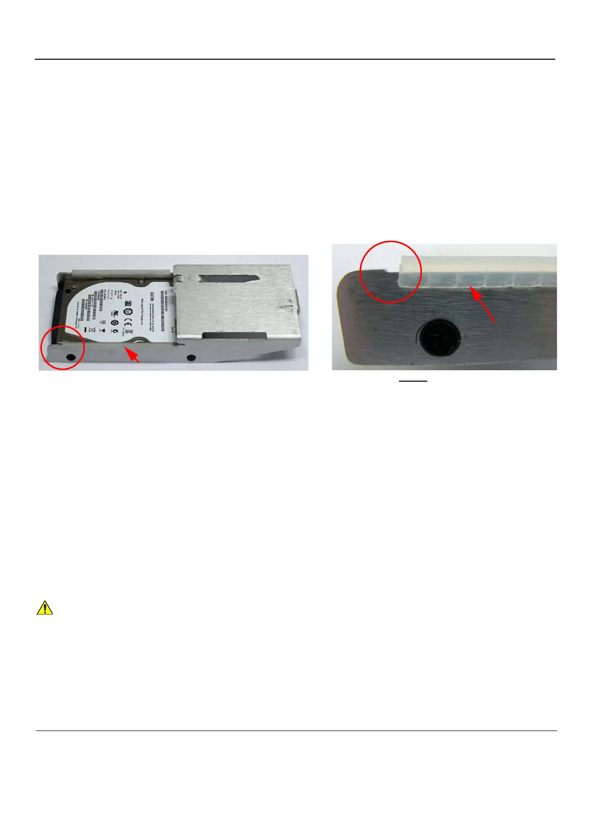
1) Using a finger and thumb to grip the metal plate firmly, slide the new hard disk into position in the
hard disk module holder - see Figure 8-153 on page 8-123.
2) Return and fasten the screw (previously removed) to secure the Hard Disk in position - refer to
Figure 8-152 on page 8-123.
3) Figure 8-152 on page 8-123.
NOTE: When inserting the hard disk and bracket into it’s slot in the Vivid S5 N / Vivid S6 N cabinet cage
assembly, check that the plastic buffer strip is properly in position as shown in Figure 8-154.
4) Return the cabinet cage assembly to the system, reconnect the cables (previously disconnected),
close the cabinet cage door and fasten securely with the two latches.
Refer to the 8-6-1-4 "Cabinet Cage Assembly Closing and Installation Procedure" on page 8-114.
5) Return the front cover, as described in the 8-2-6-4 "Front Cover Installation Procedure" on page 8-
19.
6) Return the left and right side covers, as described in the 8-2-3-4 "Left Side Cover Installation
Procedure" on page 8-7 and 8-2-2-4 "Right Side Cover Installation Procedure" on page 8-5,
7.) Turn ON power to the system.
NOTE: The formatting process limits the size of the partition “E:\” on the hard disk to approximately 120GB.
Figure 8-154 HD Bracket with Plastic Buffer Strip
For BT12 systems, use BT12 software media to perform the Hard Disk Formatting procedure as
described in “Formatting and Partitioning the Hard Disk - Automatic Procedure” on page 8-230.
Vivid S5/S6 hard disk showing plastic buffer
(indicated by arrow) position
The plastic buffer must be
set just up to the small indentation
(encircled) on the HD bracket
 Loading...


