6
CONVERTER MODE SETTING SCREEN
6-71
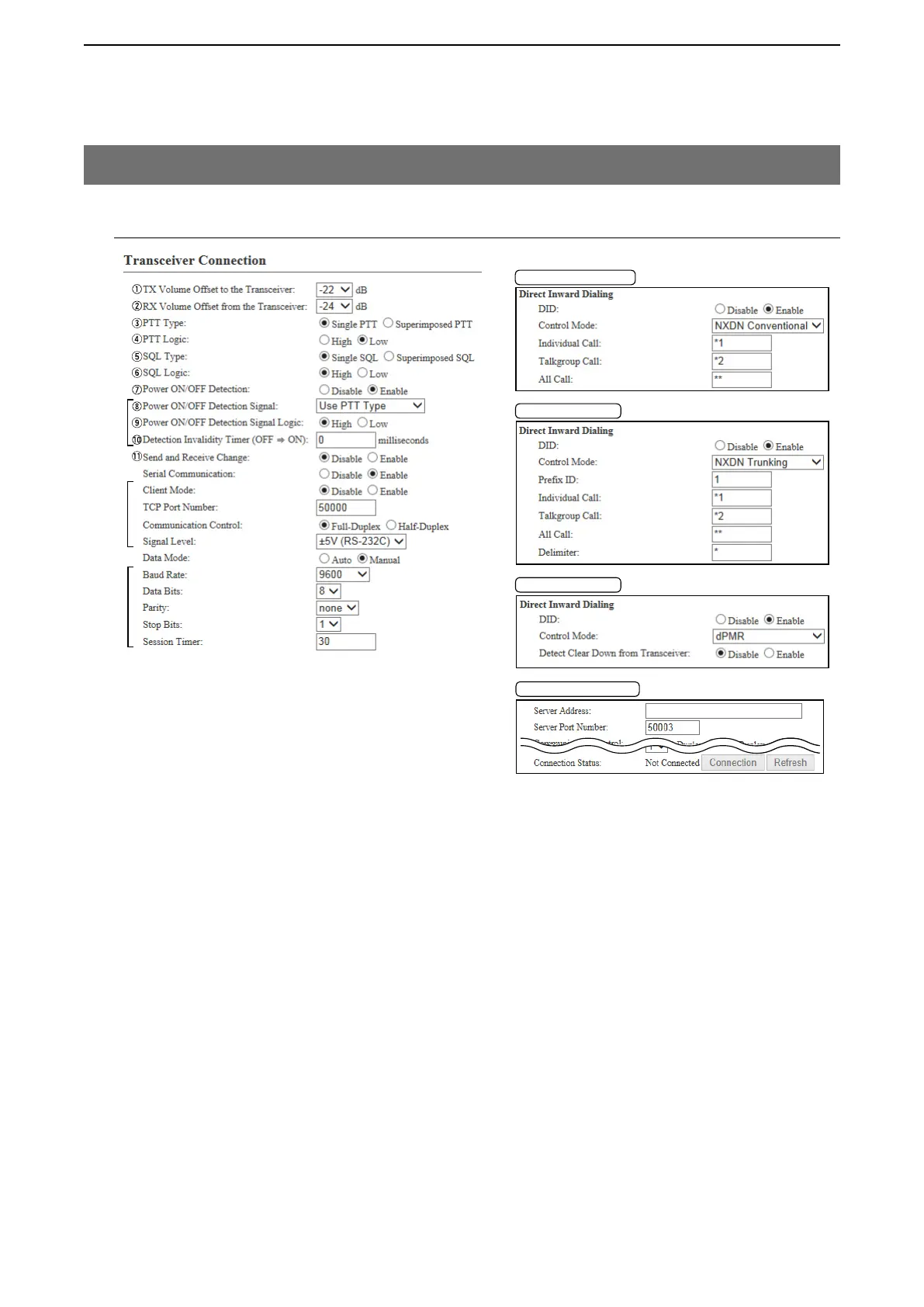
@8 All Call
Enter the characters to be recognized as an IP telephone for a group call.
(Default: **)
@9 Delimiter
Enter a character for the delimiter. This delimiter is necessary to make a call
to a digital transceiver through the VE-PG3. In addition, the delimiter function
can make an ID to make a call shorter. (Abbreviation: only “0” number)
Example: an Individual Call (*1) to Prefix ID (02) of Unit ID (0010) is “*1*2*10.”
(Default: *)
#0 Detect Clear Down from
Transceiver Select “Enable” to detect the disconnect signal from the transceiver.
(Default: Disable)
#1 Server Address
Enter the destination VE-PG3’s IP address.
#2 Server Port Number
Enter the destination VE-PG3’s port number.
(Default: EXT1=50002, EXT2=50003
)
Range: “1024” to “65535”
#3 Connection Status
Displays the connection status. Click “Connection” to connect the serial com-
munication.
9. [Port Settings] Menu (continued)
M Transceiver 1 (TRX1)/Transceiver 2 (TRX2)
[Port Settings]–[Transceiver 1 (TRX1)/[Transceiver 2 (TRX2)]
*
1
Appears only when “Enable” is selected in [Power Detection].
*
2
Appears only when “Enable” is selected in [Serial Communication].
*
3
Appears only when “Manual” is selected in [Data Mode].
*
1
*
2
*
3
!2
!3
!4
!5
!6
!7
!8
!9
@0
@1
@2
@3
@3
@3
@4
@4
@4
@5
@5
@6
@6
@7
@8
@8
@9
#0
"NXDN Trunking"
"NXDN Conventional"
"dPMR"
Client Mode:Enable
#1
#2
#3