6
CONVERTER MODE SETTING SCREEN
6-138
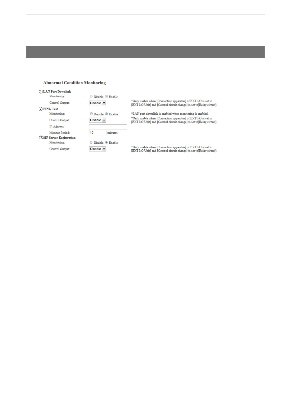
M Abnormal Condition Monitoring (continued)
10. [Expansion] Menu
[Expansion]–[Abnormal Condition Monitoring]
• This is an example.
eSIP Server Registration … Select "Enable" to detect the Connection failure (1 entry or more).
(Default: Disable)
When a Connection failure is detected, the error report is displayed on the
[SYSLOG] screen in the [Information] Menu.
Control Output
Select "Enable" to output the error detect signal from the B1/B2 terminal
(+/–). (Default: Disable)
• Select "Relay circuit" in the Control Circuit] item on the [EXT Output] (1/2),
or [EXT I/O] (1/2) screen.
While the error detect signal is sent, the VE-PG3 cannot receive signals
from the external device that is connected to the B1/B2terminal (+/–).