3
CONVERTER MODE APPLICATION
3-30
4. Operation
When the IP phone calls the VE-PG3, Radio A1 receives the call and automatically transmits it.
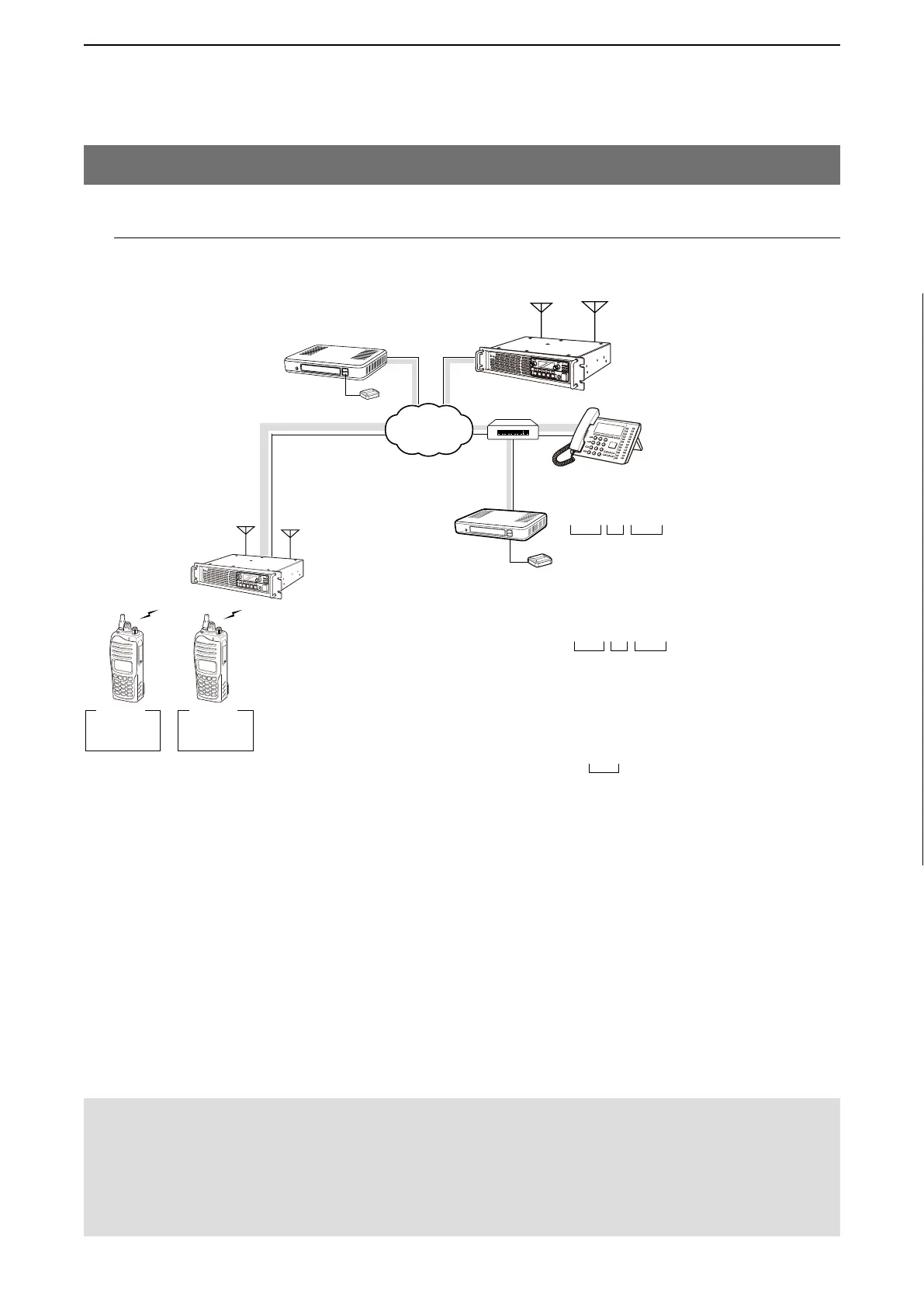
6.Operating in the NXDN Trunking mode (continued)
VE-PG3
(192.168.0.2)
[D-TRX1]
Extension No.
401
Extension No.
201
Prefix ID: 01
ID: 1
Prefix ID: 01
ID: 2
*001 01 0001
Prefix ID: 01
ID: 200
Radio A1
Radio A2
System master repeater
Site 1
Site 2
CT-24
[USB]
#001 01 1000
#123
IP
Network
An example of a digital radio network system
Special number description:
• Individual Call
• Group Call
• All Call
q Radio Call Prefix for D-TRX1 Individual Call
w Prefix ID
e ID
P
0
P
1
P
2
P
3
P
4
IP telephone
(KX-UT Series)
qwe
q Radio Call Prefix for D-TRX1 Group Call
w Prefix ID
e ID
qwe
Special Number (Assigned as All Call)
VE-PG3
(192.168.0.3)
Repeater A
CT-24
P
0
P
1
P
2
P
3
P
4
[Calling radio A1 from the IP phone.]
q
IP phone’s operator: Dial the [D-TRX] port’s extension number (*001010001).
• The communication route is connected.
w
Radio A1’s operator: When the beep sounds, hold down [PTT] and speak into the microphone to answer the call.
e
Radio A1’s operator: Release [PTT] to receive.
• All radios in the area must have same setting.
NOTE:
• Full duplex communication is impossible.
Communicate with each other by taking turns speaking.
• Pause briefly before you speak, to confirm your party has finished speaking.
• Turn ON the subscriber transceiver’s Talk Back Timer function.
• The communication route will be disconnected when the IP telephone's handset is put on the hook, or the VE-PG3 receives no
audio for the preset time (default: 15 seconds).
Note: Since the VE-PG3 can accept up to two
CT-24’s, only two digital communication lines
are available at a time, even when all three
D-TRX ports are connected to the network.