1
BEFORE USING THE VE-PG3
1-4
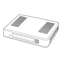
Panel description
M Front panel (continued)
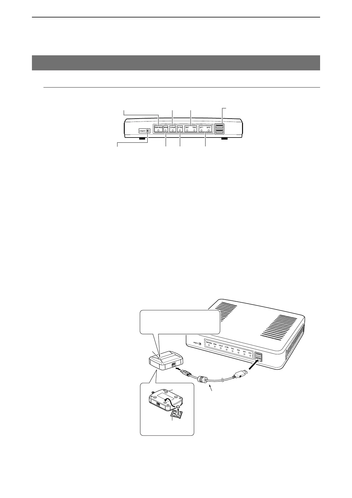
[USB] ports ………………… CAUTION: Turn OFF the power before connect or disconnect the USB flash
drive.
[Connecting a USB flash drive]
The configuration and firmware can be transferred using a USB flash drive
(purchase separately).
• Only one USB flash drive can be accepted at a time.
[Connecting the CT-24]
Connect the optional CT-24 to communicate with IC-FR5000/FR6000.
• The VE-PG3 accepts up to two CT-24s.
• When you want to connect two CT-24s and USB flash drive, a USB HUB
(self-powered HUB) is required.
Connect one CT-24 and the USB flash drive to the USB port, and connect
the other CT-24 to the USB HUB.
CT-24
USB cable
(Supplied with CT-24)
Tu rn OFF the power and
then connect the USB
cable
Cushion sheet
(Supplied with CT-24)
Cushion
NOTE:
NEVER use a USB cable other
than supplied with the CT-24.
Lights Green: Connected to the VE-PG3
Lights Orange: Communicating
LED
LED indication:
Front view
<UPDATE> button [WAN] LED [EXT] (1/2) LED
[PWR/MSG] LED
[V/RolP] LED
[D-TRX] LED
[TRX] (1/2) LED [USB] port
(USB2.0)