Datasheet 745
SMBus Controller Registers (D31:F3)
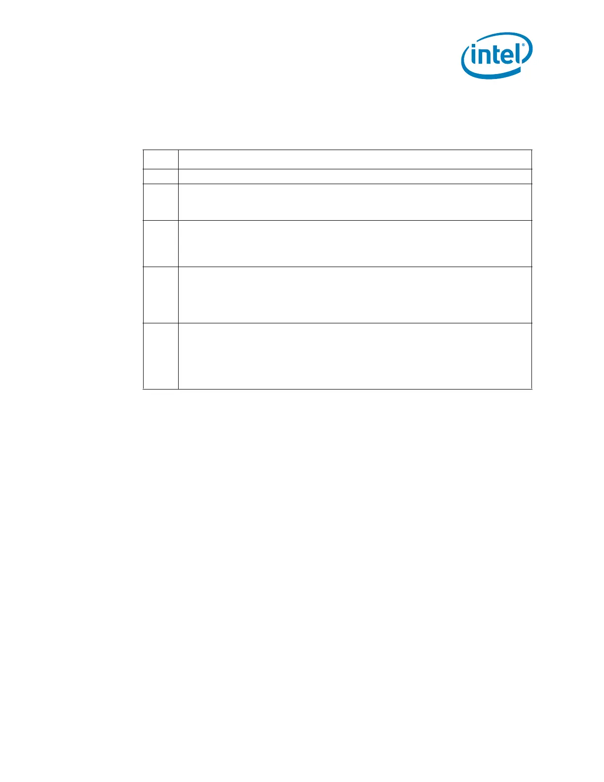
18.1.16 HOSTC—Host Configuration Register (SMBus—D31:F3)
Address Offset: 40h Attribute: R/W
Default Value: 00h Size: 8 bits
Bit Description
7:4 Reserved
3
SSRESET – Soft SMBus Reset— R/W.
0 = The HW will reset this bit to 0 when SMBus reset operation is completed.
1 = The SMBus state machine and logic in the PCH is reset.
2
I
2
C_EN — R/W.
0 = SMBus behavior.
1 = The PCH is enabled to communicate with I
2
C devices. This will change the
formatting of some commands.
1
SMB_SMI_EN — R/W.
0 = SMBus interrupts will not generate an SMI#.
1 = Any source of an SMB interrupt will instead be routed to generate an SMI#. Refer
to Section 5.20.4 (Interrupts / SMI#).
This bit needs to be set for SMBALERT# to be enabled.
0
SMBus Host Enable (HST_EN) — R/W.
0 = Disable the SMBus Host controller.
1 = Enable. The SMB Host controller interface is enabled to execute commands. The
INTREN bit (offset SMB_BASE + 02h, bit 0) needs to be enabled for the SMB Host
controller to interrupt or SMI#. Note that the SMB Host controller will not respond
to any new requests until all interrupt requests have been cleared.
 Loading...