SMBus Controller Registers (D31:F3)
752 Datasheet
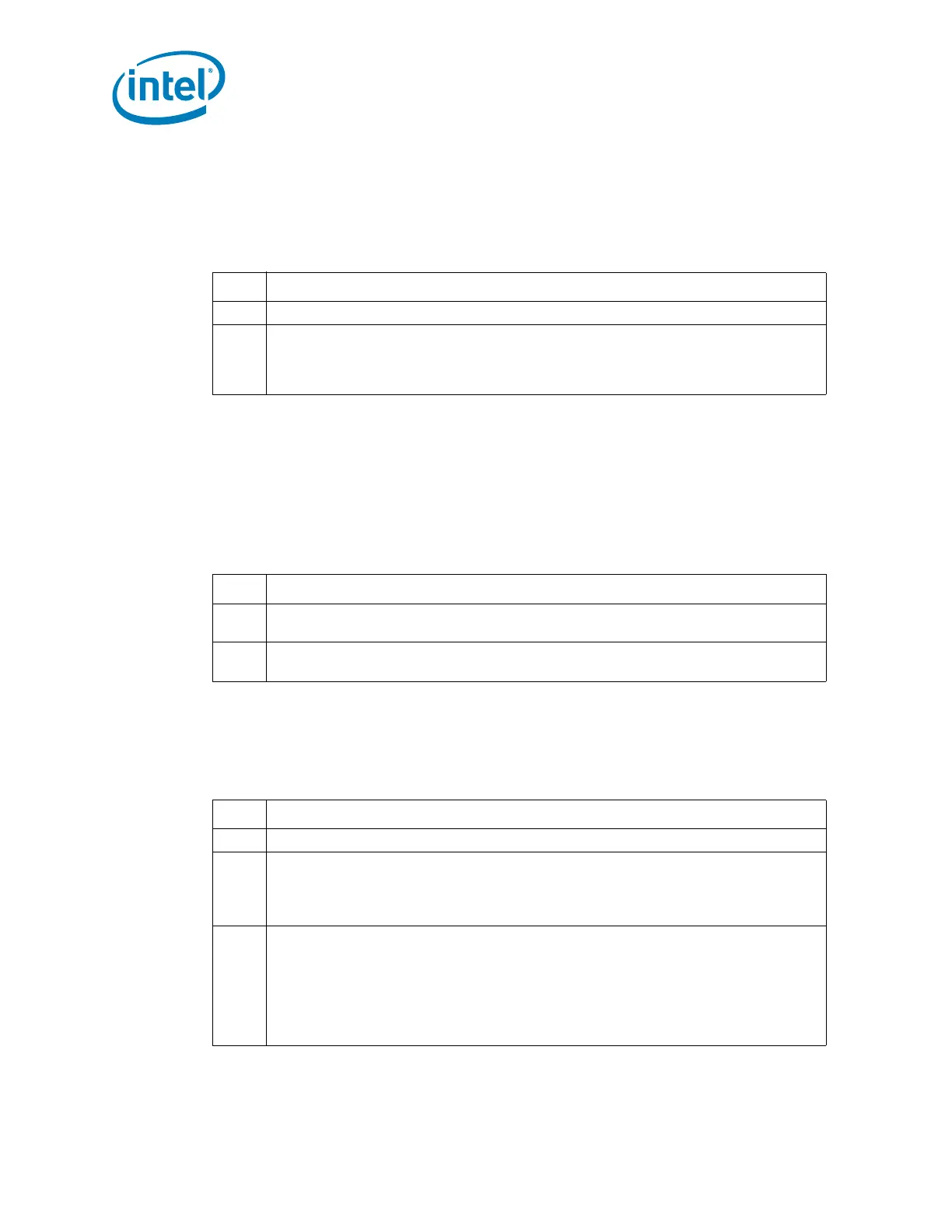
18.2.9 RCV_SLVA—Receive Slave Address Register
(SMBus—D31:F3)
Register Offset: SMB_BASE + 09h Attribute: R/W
Default Value: 44h Size: 8 bits
Lockable: No Power Well: Resume
18.2.10 SLV_DATA—Receive Slave Data Register (SMBus—D31:F3)
Register Offset: SMB_BASE + 0Ah–0Bh Attribute: RO
Default Value: 0000h Size: 16 bits
Lockable: No Power Well: Resume
This register contains the 16-bit data value written by the external SMBus master. The
processor can then read the value from this register. This register is reset by RSMRST#,
but not PLTRST#.
.
18.2.11 AUX_STS—Auxiliary Status Register (SMBus—D31:F3)
Register Offset: SMB_BASE + 0Ch Attribute: R/WC, RO
Default Value: 00h Size: 8 bits
Lockable: No Power Well: Resume
.
Bit Description
7 Reserved
6:0
SLAVE_ADDR — R/W. This field is the slave address that the PCH decodes for read and
write cycles. the default is not 0, so the SMBus Slave Interface can respond even before
the processor comes up (or if the processor is dead). This register is cleared by
RSMRST#, but not by PLTRST#.
Bit Description
15:8
Data Message Byte 1 (DATA_MSG1) — RO. See Section 5.20.7 for a discussion of
this field.
7:0
Data Message Byte 0 (DATA_MSG0) — RO. See Section 5.20.7 for a discussion of
this field.
Bit Description
7:2 Reserved
1
SMBus TCO Mode (STCO) — RO. This bit reflects the strap setting of TCO compatible
mode versus Advanced TCO mode.
0 = The PCH is in the compatible TCO mode.
1 = The PCH is in the advanced TCO mode.
0
CRC Error (CRCE) — R/WC.
0 = Software clears this bit by writing a 1 to it.
1 = This bit is set if a received message contained a CRC error. When this bit is set, the
DERR bit of the host status register will also be set. This bit will be set by the
controller if a software abort occurs in the middle of the CRC portion of the cycle or
an abort happens after the PCH has received the final data bit transmitted by an
external slave.
 Loading...