Datasheet 753
SMBus Controller Registers (D31:F3)
18.2.12 AUX_CTL—Auxiliary Control Register (SMBus—D31:F3)
Register Offset: SMB_BASE + 0Dh Attribute: R/W
Default Value: 00h Size: 8 bits
Lockable: No Power Well: Resume
.
18.2.13 SMLINK_PIN_CTL—SMLink Pin Control Register
(SMBus—D31:F3)
Register Offset: SMB_BASE + 0Eh Attribute: R/W, RO
Default Value: See below Size: 8 bits
Note: This register is in the resume well and is reset by RSMRST#.
This register is only applicable in the TCO compatible mode.
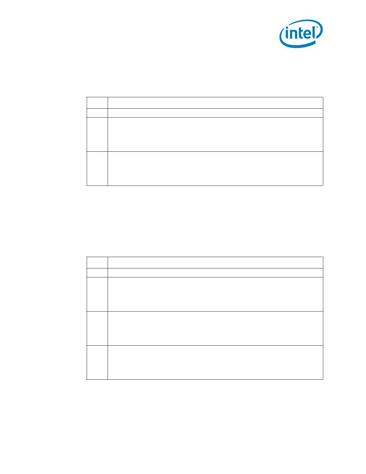
Bit Description
7:2 Reserved
1
Enable 32-Byte Buffer (E32B) — R/W.
0 = Disable.
1 = Enable. When set, the Host Block Data register is a pointer into a 32-byte buffer, as
opposed to a single register. This enables the block commands to transfer or receive
up to 32-bytes before the PCH generates an interrupt.
0
Automatically Append CRC (AAC) — R/W.
0 = The PCH will Not automatically append the CRC.
1 = The PCH will automatically append the CRC. This bit must not be changed during
SMBus transactions or undetermined behavior will result. It should be programmed
only once during the lifetime of the function.
Bit Description
7:3 Reserved
2
SMLINK_CLK_CTL — R/W.
0 = The PCH will drive the SMLink0 pin low, independent of what the other SMLink logic
would otherwise indicate for the SMLink0 pin.
1 = The SMLink0 pin is not overdriven low. The other SMLink logic controls the state of
the pin. (Default)
1
SMLINK1_CUR_STS — RO. This read-only bit has a default value that is dependent on
an external signal level. This pin returns the value on the SMLink1 pin. This allows
software to read the current state of the pin.
0 = Low
1 = High
0
SMLINK0_CUR_STS — RO. This read-only bit has a default value that is dependent on
an external signal level. This pin returns the value on the SMLink0 pin. This allows
software to read the current state of the pin.
0 = Low
1 = High
 Loading...