● If the count input rises and the reset input falls at the same time, the count input is ignored
and preset is executed.
● An OT instruction can be entered immediately after a counter instruction.
■
Precautions for programming
● The counter set value area CS and counter elapsed value area CE both occupy 32-bit areas.
● When specifying a 16-bit device such as DT for the operand S of CT16 instruction, the area
used is for 16-bit data.
● When U0 is specified for the setting value, the count-up operation is performed when the
instruction is executed and the counter contact C turns ON.
■
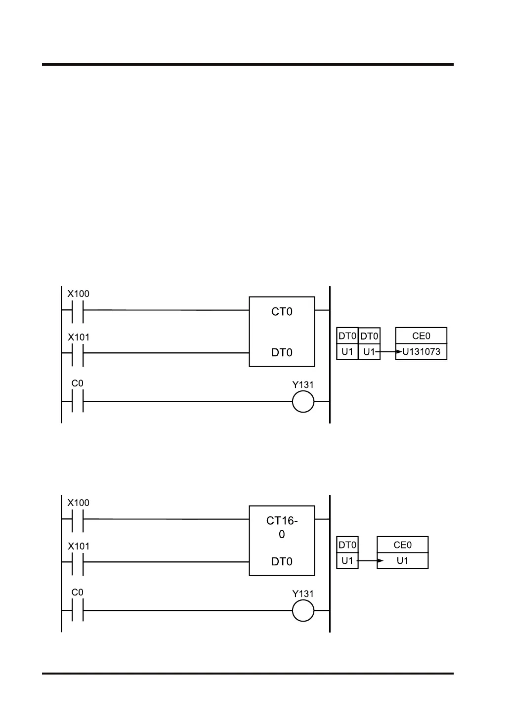
Difference between CT and CT16 instructions
CT instruction (When specifying operand S=16-bit device)
32-bit data U131073 (H20001) written in DT0 to DT1 is treated as the counter setting value.
U131073 is set in the elapsed value area CE0 when the input of X101 falls.
CT16 instruction (When specifying operand S=16-bit device)
16-bit data U1 (H1) written in DT0 is treated as the counter setting value. U1 is set in the
elapsed value area CE0 when the input of X101 falls.
3.21 CT16 (16-bit Counter)
3-64 WUME-FP7CPUPGR-12

 Loading...


