■
Operation Example
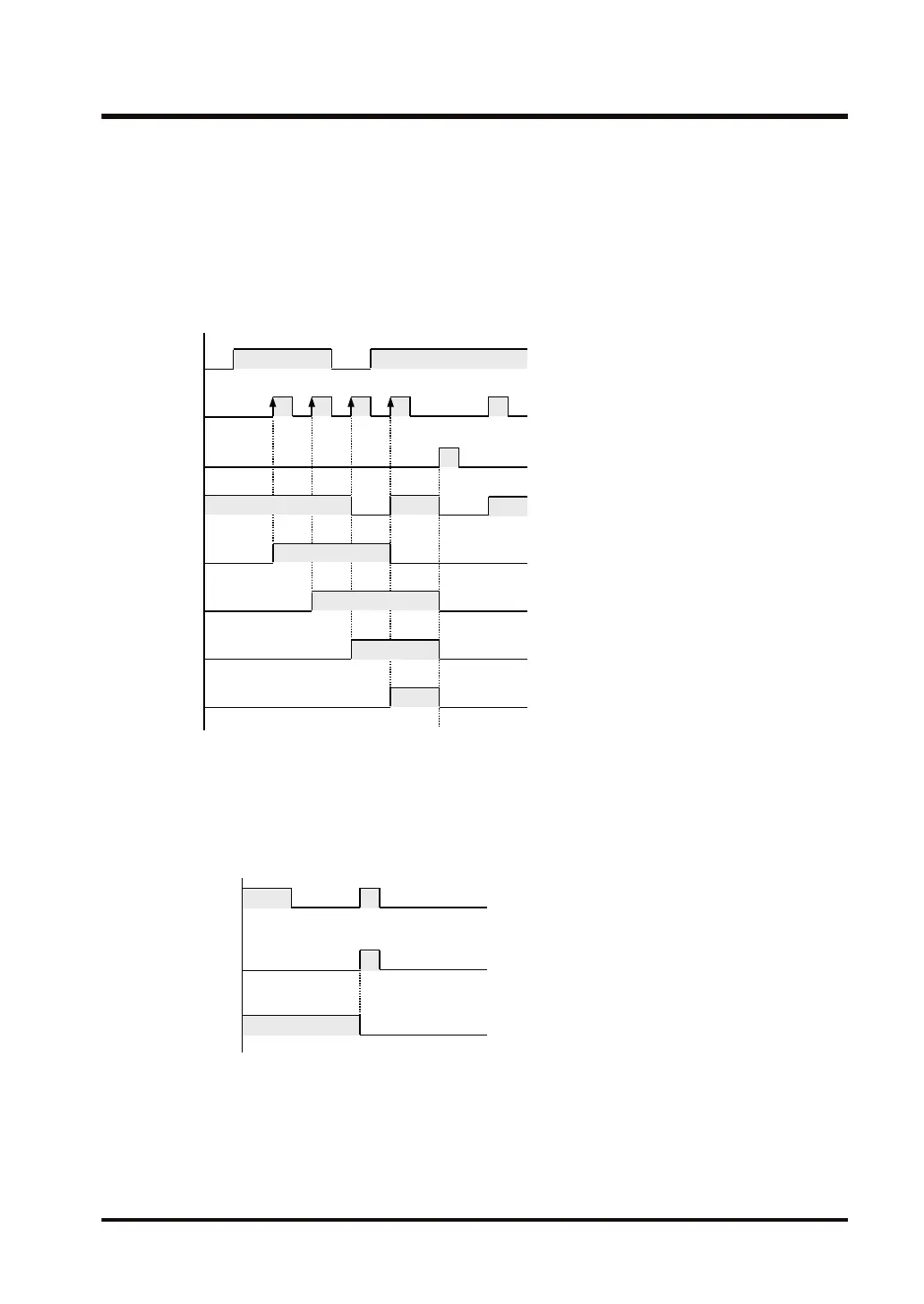
X100
X101
X102
R30
R31
R32
R33
R34
1) When X101 turns ON while X102 is OFF, the contents of WR3 (internal relays R30 to
R3F) are shifted by 1 bit to the left.
2) In the bit that has become blank due to left shifting (R30), 1 is set when X100 is ON and
0 is set when X100 is OFF.
3) When X102 turns ON, the contents of WR3 are reset to 0.
③
■
Precautions for programming
● The data input, shift input, and reset input are required for the SR instruction.
● When reset input and shift input rise simultaneously, reset input is prioritized.
● Note that if a hold-type memory area is specified for the shift register, it will not be
automatically reset upon power ON.
● When combining a shift register instruction with an AND stack instruction or pop stack
instruction, make sure that the syntax is correct.
3.23 SR (Shift Register)
WUME-FP7CPUPGR-12 3-71

 Loading...


