1) DF (leading edge differential) instruction
2) Count input for CT (counter) instruction
3) Count input for UDC (up-down counter) instruction
4) Shift input for SR (shift register) instruction
5) Shift input for LRSR (left and right shift register) instruction
6) Differential execution type high-level instruction (instruction specified by p and instruction name)
■
Operation Example
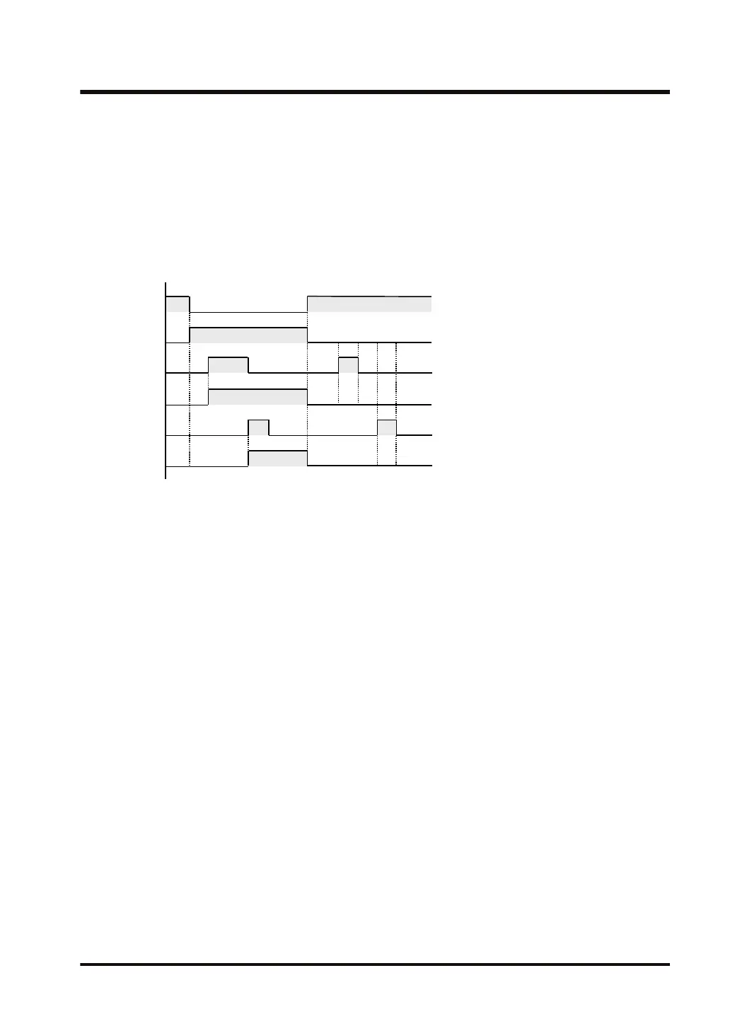
X100
Execution
condition
X101
Y131
X102
Y132
■
Operation of differential instructions between MC and MCE
● If the differential instruction is used between MC and MCE, the output obtained differs
depending on the execution condition of MC and the input timing of the differential instruction
as shown below.
3.25 MC (Master Control Relay), MCE (Master Control Relay End)
WUME-FP7CPUPGR-12 3-77

 Loading...


