(Note 7) Can be specified only when the operation unit is a single-precision floating point real number (SF).
(Note 8) Can be specified only when the operation unit is a double-precision floating point real number (DF).
■
Outline of operation
Compares signed data specified in [S1] with signed data specified in [S2].
Connects in parallel as a contact connected when the comparison result is in the specified state
(such as =, <, or >).
■
Comparison result and operation
Relationship between [S1] and [S2] [S1] < [S2] [S1] = [S2] [S1] > [S2]
Comparison instruction OR= OFF ON OFF
OR<> ON OFF ON
OR> OFF OFF ON
OR>= OFF ON ON
OR< ON OFF OFF
OR<= ON ON OFF
(Note 1) ● "< >" represents "≠".
● ">=" represents "≥".
● "<=" represents "≤".
■
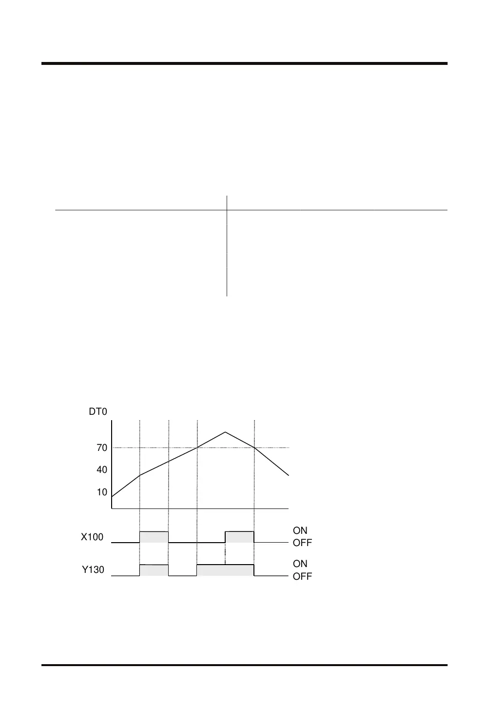
Operation Example
Program operation of "OR >=" in the ladder diagram
When external output X100 turns ON, or the result of comparison between the value of DT0
and K70 is DT0 > K70, external output Y130 turns ON.
70
DT0
40
10
X100
ON
OFF
Y130
ON
OFF
■
Precautions for use
● The "OR=", "OR<>", "OR>", "OR>=", "OR<", and "OR<=" instructions are initiated from the
bus bar.
● The "OR=", "OR<>", "OR>", "OR>=", "OR<" and "OR<=" instructions can be used in series.
3.48 OR=, OR<>, OR>, OR>=, OR<, OR<= (Data Comparison (OR))
3-140 WUME-FP7CPUPGR-12

 Loading...


