■
Outline of operation
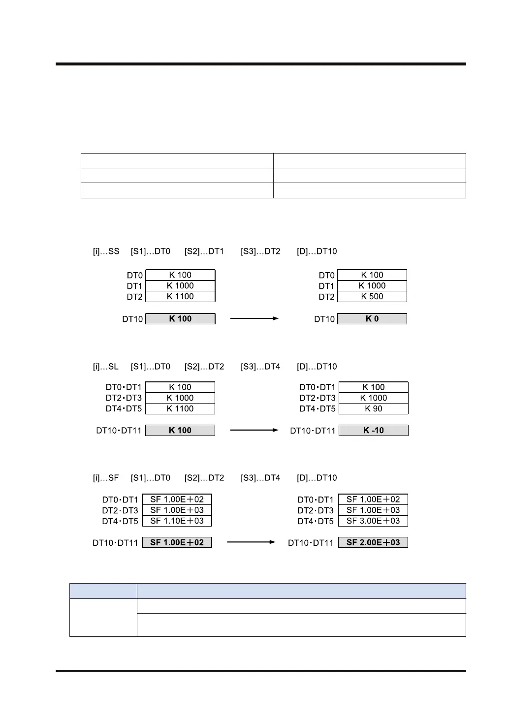
● The output value, to be stored in the device address specified by [D], is controlled based on
whether or not the input value specified by [S3] falls within the range bounded by the upper
and lower limits set in [S1] and [S2].
● The output value [D] stores the following data.
Lower limit [S1] > Input value [S3] Input value [S3] - Lower limit [S1] → Output value [D]
Upper limit [S2] < Input value [S3] Input value [S3] - Upper limit [S2] → Output value [D]
Lower limit [S1] ≤ Input value [S3] ≤ Upper limit [S2] 0 → Output value [D]
■
Processing
Example 1) Operation unit: 16 bits (SS)
Example 2) Operation unit: 32 bits (SL)
Example 3) Operation units: Single precision floating point real number (SF)
■
Flag operations
Name Description
SR7
SR8
(ER)
To be set in the case of out-of-range in indirect access (index modification).
To be set when [S1] is larger than [S2].
10.16 BAND (Deadband Control)
WUME-FP7CPUPGR-12 10-63

 Loading...


