● Using the UNITSEL instruction, specify the slot number (U0) and the COM. port number
(U1).
● In the SEND instruction, specify and execute PLC's starting address (DT100) and data
amount (U2), MODBUS function code to be used (16: H10), and partner station number
(H01) and starting address (H0). Check addresses of connected devices in the instruction
manuals of devices.
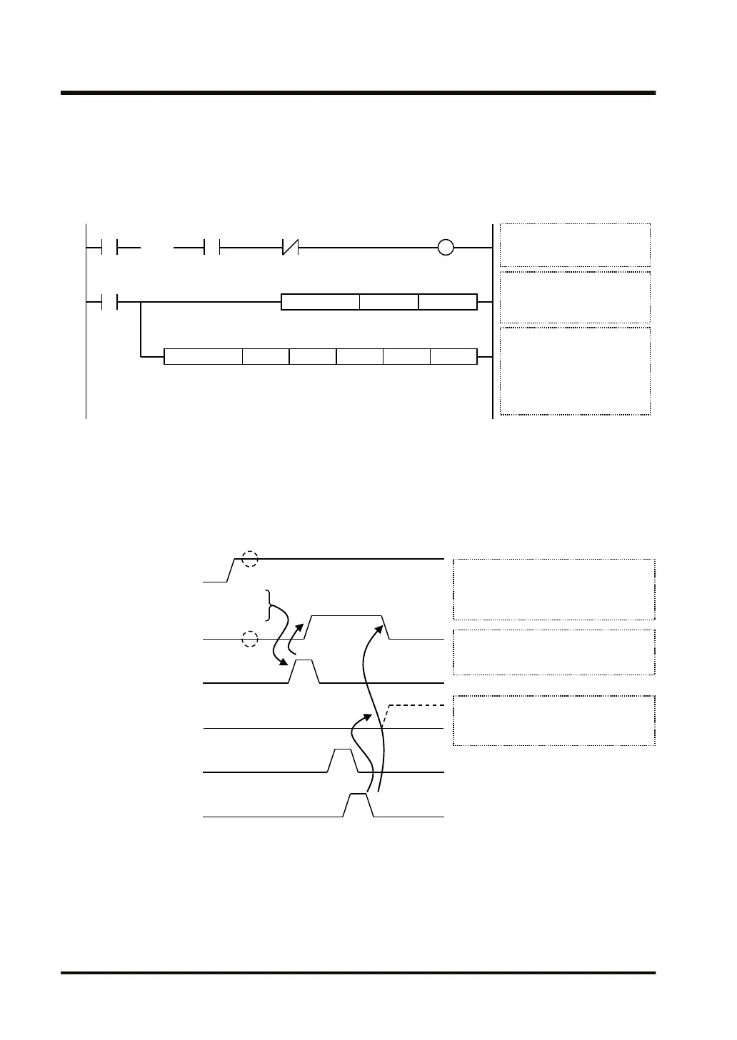
R100
UNITSEL U0 U1
SEND.US DT0H1001 H0DT100 U2
SEND
execution
Settings for the communication
port
S1: Slot 0 (U0)
S2: COM1 (U1)
SEND execution conditions
Clear to send flag: ON
Sending flag: OFF
SEND processing
S: Data storage area (DT100)
n: Sent data amount (U2)
D1: MODBUS code (H10) and
Partner station no. (H01)
D2: Destination address (H0)
D3: Execution result code (DT0)
Master
communication
clear to send flag
Master
communication
sending flag
(Note 1) Operand [D1] of SEND instruction is specified by combining two hexadecimal digits of MODBUS
function code with two hexadecimal digits of partner device station number. When the MODBUS
function code is 16, [D1] H10 should be specified.
(Note 2) When the partner device is FP series PLC, Operand [D2] of SEND instruction can be specified using
the device number.
■
Time chart (in the case of SCU)
sending flag
(YC, YD, YE, YF)
sent flag
(Y0, Y1, Y2, Y3)
Sending data
Response reception
processing
clear to send flag
(XC, XD, XE, XF)
SEND instruction executable conditions
Clear to send flag (XC, XD, XE, XF):
ON
Sending flag (YC, YD, YE, YF): OFF
Sent flag (Y0, Y1, Y2, Y3):
Normal completion: OFF
Abnormal completion: ON
Sending flag (YC, YD, YE, YF):
While sending: ON; Sending done:
OFF
Check that the
flag is OFF
Check that the
flag is ON
15.6 SEND (MODBUS Master: Function Code Specification)
15-40 WUME-FP7CPUPGR-12

 Loading...


