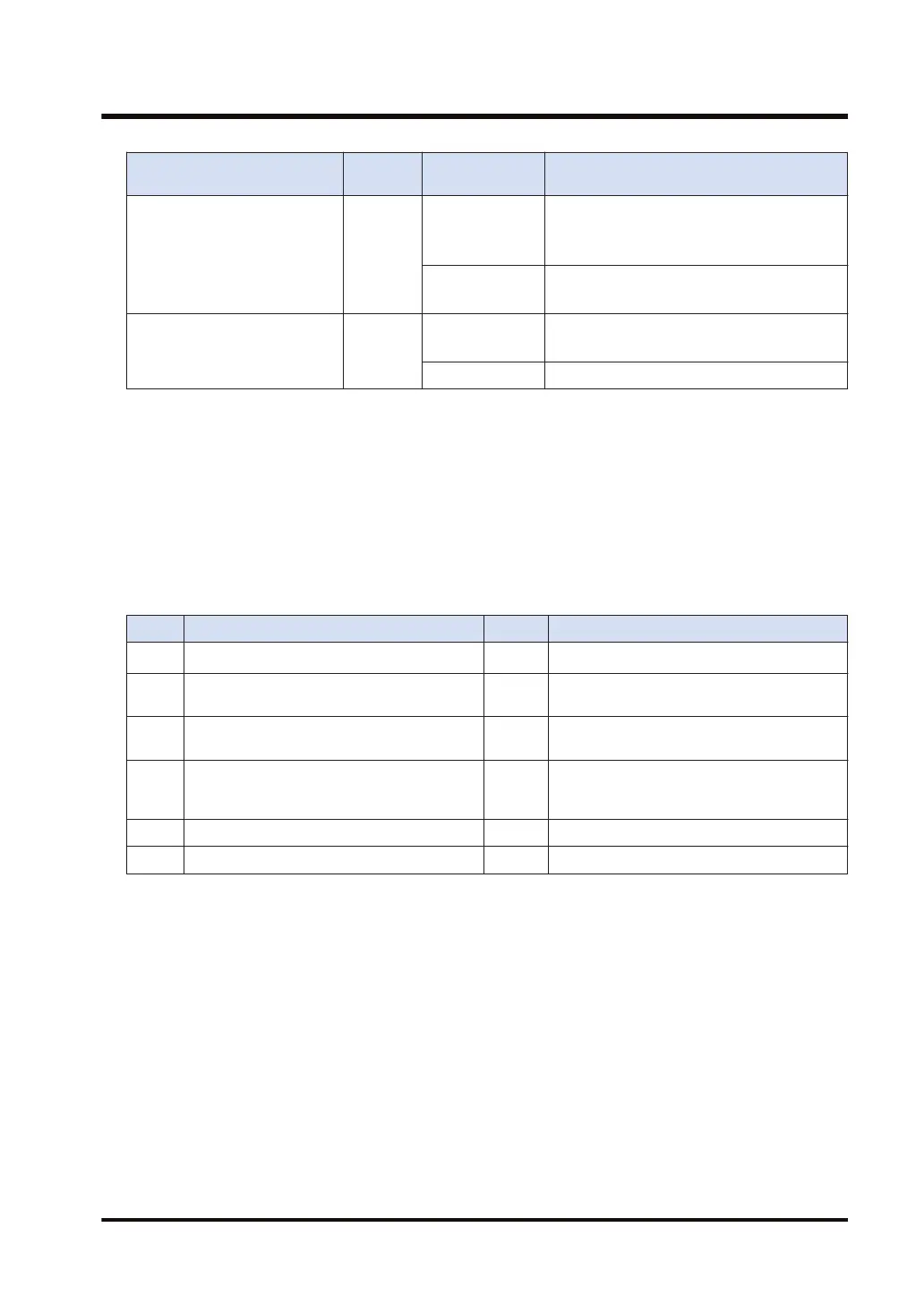
Types of device to be
specified for [S]
Transfer
method
Number of sent
data [n]
Value that can be specified for high bytes
of [D1]
16-Bit device:
WX, WY, WR, WL, DT, LD
Register
transfer
1
H6: Preset single register (06)
HF: Force multiple coils (15)
H10: Preset multiple registers (16)
2 to 127
HF: Force multiple coils (15)
H10: Preset multiple registers (16)
1-Bit device:
X, Y, R, L, DT.n, LD.n
Bit
transfer
1
H5: Force single coil (05)
HF: Force multiple coils (15)
2 to 2040 HF: Force multiple coils (15)
● The amount of sent data [n] is specified in words for the register transfer, and in bits for the
bit transfer.
● Operand [D1] is specified as a combination of a two-digit hexadecimal MODBUS function
code and a two-digit hexadecimal partner station number.
Example: Specify "H100A" in the case of MODBUS function code 16 (preset multiple
registers) and station number 10.
● In the case of SCU, when "0" is specified for the partner station number, global transfer is
selected. In this case, there is no response message from the destination.
■
Execution result code [D3]
Code Description Code Description
H0 Normal end H6
Reception error
(Note 1)
H1
The communication port is being used in the
master communication.
H7
I/O allocation shortage error
(Note 2)
H2
The communication port is being used in the
slave communication.
H8001 Function code error
H3
The number of master communication
instructions simultaneously used is
exceeded.
H8002 Device number error (out of range)
H4 Transmission timeout H8003 Device quantity error (out of range)
H5 Response reception timeout
(Note 1) It occurs when an abnormal telegram is received. When there is a format error in the header of an
individual protocol, the communication discards the received data and a response reception timeout
occurs.
(Note 2) It occurs when the communication control I/O relays corresponding to the communication port (master
communication clear to send flag, master communication send active flag, master communication
send done result relay)are not allocated as I/O words of the CPU unit in the I/O map. It occurs only
when the number of user connections of ET-LAN is expanded and this instruction is executed
specifying the expanded connections.
■
Sample program (in the case of SCU)
● This program sends the command from the COM1 port of the CPU unit, and then writes the
content of PLC's data registers DT100 to DT101 into the data areas 400001 to 400002 of the
external device (station number 1).
● This program checks that the master mode is on (XC) and that sending is not in progress in
the same port (YC), and then starts up the SEND instruction.
15.6 SEND (MODBUS Master: Function Code Specification)
WUME-FP7CPUPGR-12 15-39

 Loading...


