Operand Parameter Range Settings
[S+6]
Link relay transmission
start number
U0 to U63 Link relay transmission start number
[S+7]
Link relay transmission
size
U0 to U64 Link relay transmission size
[S+8]
Link register
transmission start
number
U0 to U127 Link register transmission start number
[S+9]
Link register
transmission size
U1 - U127
As for the link register transmission size, up to 127
words can be sent.
■
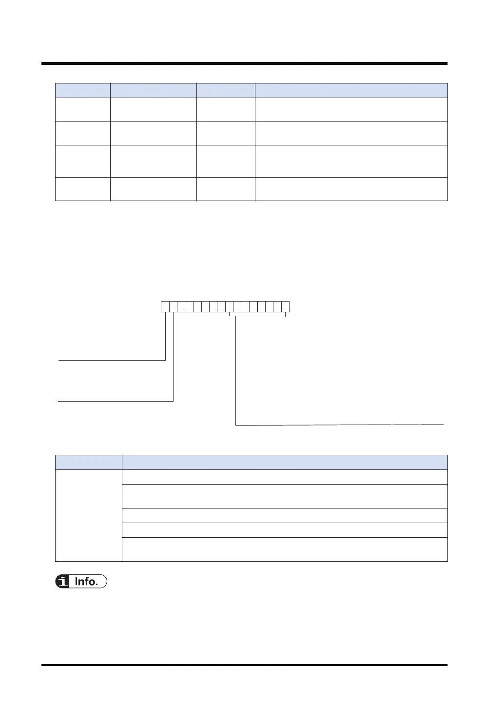
Content of the processing result [D]
● Execution results are stored in the area of one word.
● The execution result code in the low byte is valid when the process in-progress flag of bit 15
is zero.
● If an error occurs, the execution result flag (bit 14) is turned ON. The description of the error
is stored in the execution result code (bits 0 to 7).
0: Process done
1: In-progress
Process in-progress flag
0: Normal completion
1: The communication port specified by UNITSEL instruction
is invalid
2: Setting error
3: Mode change error
4: Communication port occupied
5: Change request parameter inconsistency (At the start/end
of the setting process, parameters specified by operands
are inconsistent)
7: Unit number setting on the front panel of the multi-wire link
unit (When the switch is not 0)
Execution result code
Execution result flag
0: Normal completion
1: Abnormal completion
■
Flag operations
Name Description
SR7
SR8
(ER)
To be set in the case of out-of-range in indirect access (index modification, pointer access).
To be set when the FP7 multi-wire link unit does not exist in the slot that is specified by
UNITSEL.
To be set when the device specified by [S] is out of the range.
To be set when the number of words specified by [n] is out of the available range.
To be set when the instruction is executed in an interrupt program and the FP7 multi-wire
link unit is the target.
● For details of sample programs, refer to "16.7 PMSET / pPMSET (Change of MEWNET-W2
Parameters)".
16.6 PMSET / pPMSET (Change of MEWNET-W Parameters)
16-22 WUME-FP7CPUPGR-12

 Loading...


